



Table of contents: No-load stepper motor (SM) voltage…🠇 Stepper motor idle resistance values 🠇 Idle air control valve type 🠇 Influence of external factors 🠇 Checking the stepper motor (general…🠇 Low idle speed 🠇 Stepper motor testing 🠇 Intake Manifold Heater (IMH) 🠇 Intake manifold heater (IMH) voltage…🠇 Intake manifold heater (IMH)…🠇 Intake manifold heater type 🠇 Rapid test 🠇 Intake Manifold Heater Tests 🠇
Idle Speed Stepper Motor (ISSM) (see illustration 12.19) is an actuator that the electronic control unit uses to automatically control the idle speed at normal idle speed and during engine warm-up. When closed, the throttle valve is fixed in a position that allows a small amount of air to pass through. Therefore, the throttle position has no effect on idle speed.
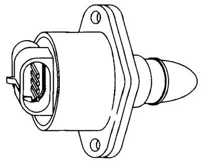
12.19 Idle Speed Stepper Motor (ISSM)
The bypass channel relative to the throttle valve is located in the throttle body. The valve is located in the channel. When the valve moves, air passes through the passage and this affects the idle speed. Then the idle speed depends on the position of the pneumatic valve of the stepper motor, located in the bypass channel.
The electronic control unit controls the stepper motor through two windings of the electric motor. Each pulse coming from the electronic control unit causes the stepper motor to rotate step by step (those. 1/1 turn or 0.04 mm).
When additional power consumers are turned on, such as headlights or a heater fan, the idle speed will decrease. In this case, the electronic control unit will open the stepper motor valve to maintain the previous idle speed.
When the engine is turned off, power is supplied to the stepper motor for 4-5 seconds, thus the electronic control unit closes the pneumatic valve (preventing the engine from starting spontaneously). After a few seconds, the electronic control unit activates the pneumatic valve, which opens slightly, and the engine is ready for the next start.
If the engine speed exceeds idle speed, the stepper motor will move the pneumatic valve to a position where the air supply is completely stopped. When braking, the stepper motor will open the bypass channel, allowing additional air to enter the intake manifold. This helps to reduce excessive emissions of harmful substances into the atmosphere during braking.
No-load stepper motor (SM) voltage values
Terminal numbers
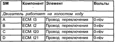
See Figure 12.2
Stepper motor idle resistance values
Terminal numbers

Idle air control valve type
Stepper motor.
Influence of external factors
- Basic throttle valve installation
- Vacuum leak
- Throttle valve sticking
- Poorly adjusted or stuck throttle cable
Checking the stepper motor (general check)
1. Inspect the stepper motor multi-pin connector for signs of corrosion or damage.
2. Make sure the connector terminal pins are installed properly and have good contact with the idle stepper motor multi-pin connector.
Low idle speed
1. Allow the engine to idle.
2. Make sure that the idle speed corresponds to the nominal values.
3. Increase engine load by turning on the headlights, rear window defroster and heater fan. The idle speed should change.
4. If no deviations were found during the check, then most likely the condition of the stepper motor will also be normal.
Stepper motor testing
1. Remove the stepper motor from the intake manifold.
2. Make sure the air duct is clean. Clean the channel if necessary.
3. Make sure that the shaft and cone rotate freely in the motor armature.
4. Install the stepper motor.
5. Disconnect the multi-pin connector of the stepper motor or ECU.
6. Measure the resistance of the motor windings at terminals A and D, as well as at terminals B and C.
7. Compare the obtained results with the values given in the specifications.
8. Connect all multi-pin connectors.
9. Connect the negative probe of the oscilloscope or voltmeter to ground on the engine.
10. Connect the positive probe of the oscilloscope or voltmeter to the No. A terminal of the stepper motor signal wire.
11. Let the engine idle.
12. Turn components on and off: for example: rear window defroster, high beam headlights and heater blower. Set the rear window defroster and heater fan to maximum mode. The voltage should switch from zero to battery voltage as the motor winding supplies power.
13. Repeat the tests at terminals No. B, No. C and No. D of the stepper motor signal wire.
14. If there is no signal, check the continuity of the wiring between the multi-pin connector of the electronic control unit and the stepper motor.
15. If the stepper motor wiring is normal, then check the power and ground contacts of the electronic control unit. If the contacts are OK, then the electronic control unit may be faulty.
Intake Manifold Heater (IMH)
Intake Manifold Heater (IMH) (see illustration 12.20) it is designed to heat the throttle body so that it does not freeze in cold weather. When the engine is running, the heater operates continuously. A heater with a positive temperature coefficient (PTC) allows the current to quickly heat the throttle body during the warm-up process. As the heater heats up, the resistance increases and the current decreases.
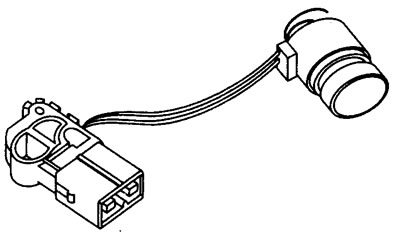
12.20 Intake Manifold Heater (IMH)
Intake manifold heater (IMH) voltage values
Terminal numbers
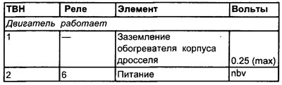
See Figure 12.2
Intake manifold heater (IMH) resistance

Intake manifold heater type
Positive temperature coefficient (PTC)
Rapid test
- Start the engine from a cold state and touch the area around the throttle body. If the heater is working, this area should become very hot in a very short time. Be careful not to burn your fingers!
Intake Manifold Heater Tests
1. Allow the engine to idle.
2. Connect the negative probe of the voltmeter to ground.
3. Connect the positive probe of the voltmeter to the heater power connector.
4. The voltmeter should show the nominal voltage of the battery.
5. Lack of supply voltage.
6. Check the output voltage from the relay.
7. Check the continuity of the wires between the relay and the heater.
8. If battery voltage is supplied, but the heater does not use it.
9. Check the heater resistance.
10. Check the heater grounding.