
Charcoal filter solenoid valve (CFSV) and a coal tank are used to reduce the emission of fuel vapors into the atmosphere. The carbon tank accumulates and absorbs fuel vapors, which, under certain operating conditions, move into the intake manifold for further combustion.
Charcoal filter solenoid valve (CFSV)
When the engine stops, the carbon filter solenoid valve will close (see illustration 12.29). With the ignition on, the charcoal filter solenoid valve remains closed until the engine has warmed up to normal operating temperature and the throttle is partially opened. As soon as the electronic control unit activates the carbon filter solenoid valve, fuel vapors enter the intake manifold for further combustion.
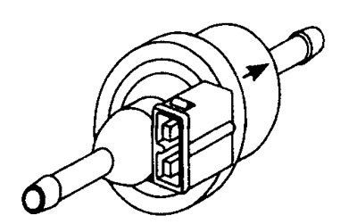
12.29 Charcoal filter solenoid valve (CFSV)
The charcoal filter solenoid valve remains closed when the engine is cold and during idling. Once the coolant temperature reaches normal operating temperature and the throttle is partially opened (in the range of 10.4°and 84°), then the electronic control unit will switch (turn on and off) carbon filter solenoid valve with 54% duty cycle.
After the engine is switched off, the closed valve prevents the engine from spontaneous starting when it is idle.
Charcoal Filter Solenoid Valve Voltage Values
Terminal numbers
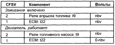
See illustration 12.2
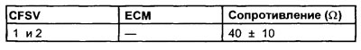
Carbon filter solenoid valve resistance value
Charcoal Filter Solenoid Valve Duty Cycle
54% at normal operating temperature with throttle half open.
Influence of external factors
- Damaged or leaking vacuum hoses and joints
Charcoal Filter Solenoid Check (CFSV) (general check)
1. Inspect the charcoal filter solenoid valve multi-pin connector for signs of corrosion or damage.
2. Check that the connector terminal pins are installed properly and make good contact with the carbon filter solenoid valve multi-pin connector.
3. Verification is quite simple. Two wires are connected to the carbon filter solenoid valve connector: a power wire and a ground wire.
4. Peel back the rubber insulation (where possible) to the multi-pin connector of the charcoal filter solenoid valve or connect the outlet block (WWII) between the multi-pin connector of the electronic control unit and the electronic control unit.
5. Connect the negative lead of an oscilloscope or voltmeter to ground on the motor.
6. Connect the positive lead of an oscilloscope or voltmeter to terminal #1 of the carbon filter solenoid valve signal wire.
7. Oscilloscope is a useful tool to check the switching waveform (see illustration 12.30). If the oscilloscope is not available, continue checking for voltage.
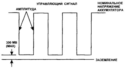
12.30 Typical input signal waveform to the carbon filter solenoid valve from the electronic control unit
Checking the pulsed operation of the carbon filter solenoid valve
1. Warm up the engine to normal operating temperature.
2. Raise the engine speed to approximately 2000 rpm and let the engine run at that speed.
3. Check the switching impulse.
4. If there is no pulse, perform the following electrical checks.
Charcoal Filter Solenoid Check (electrical checks)
1. Turn on the ignition, check for battery voltage at the supply terminal No. 2 of the carbon filter solenoid valve.
2. If there is no voltage, trace the wiring back to the relay output terminal.
3. Check for voltage at terminal #1 of the carbon filter solenoid valve, which should be approximately at the nominal battery voltage.
4. If there is no voltage, check the resistance of the carbon filter solenoid valve.
5. Disconnect the multi-pin connector of the electronic control unit.
6. Turn the ignition on to supply voltage to the carbon filter solenoid valve.
7. Using a jumper wire, briefly connect the switch terminal (contact pin no. 22) in the multi-pin connector of the electronic unit with grounding.
8. If the carbon filter solenoid valve works, the electronic control unit may be faulty.
9. If the carbon filter solenoid valve does not work, check for battery voltage at terminal No. 22.
10. If voltage is present, the electronic control unit may be faulty.
No voltage
11. Disconnect the multi-pin connector from the carbon filter solenoid valve.
12. Connect a voltmeter between terminals #1 and #2 on the multi-pin connector.
13. Using a jumper wire, connect the switching terminal for a very short time (contact pin no. 22) in the multi-pin connector of the electronic unit with grounding.
14. If the voltmeter indicates the nominal voltage of the battery, then the charcoal filter solenoid valve wiring is OK. Most likely the charcoal filter solenoid valve is faulty.
15. If the voltmeter does not indicate the nominal voltage of the battery, then check the conductivity of the wiring between the multi-pin connector of the carbon filter solenoid valve and the switching terminal of the electronic control unit.
Oxygen sensor (OS)
The closed-loop oxygen sensor signal causes the electronic control unit to change the injector stroke in such a way that the composition of the air-fuel mixture is kept as close to the stoichiometric ratio as possible. By controlling the fuel injection stroke, under most operating conditions, so that the air-fuel ratio is always within a small window around the Lambda point (i.e. Lambda = 0.981.04), at which almost complete combustion is achieved.
The oxygen sensor works in a closed circuit when the coolant temperature is above 45°C. If the coolant temperature is below 45°C or the engine load is at or above normal, the ECU will operate in open loop. When operating in open loop, the electronic control unit adjusts the air-fuel mixture, making it richer or leaner than required for the stoichiometric ratio. This prevents erratic engine operation, such as when accelerating at wide open throttle.
In order for the oxygen sensor to reach its maximum operating temperature as quickly as possible after starting the engine, it contains a heating element.
The supply voltage to the oxygen sensor heater comes from terminal No. 6 of the fuel pump relay. Therefore, the oxygen sensor heater will only function when the engine is running.
Oxygen Sensor Voltage Values (OS)
Terminal numbers
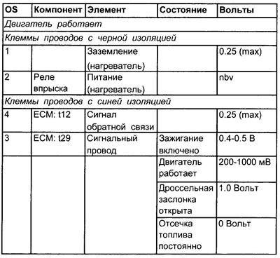
See illustration 12.2
Switching frequency
Intervals approximately 1 sec
Influence of external factors
- Poor oxygen sensor ground
- Dirty oxygen sensor
- Vacuum leaks
- Malfunction of the ignition system or fuel system
- Oil thinning
- Clogged air filter
- Leaded gasoline
- Low fuel pressure
- Exhaust leaks (master oxygen sensor)
Checking the signal from the oxygen sensor
1. Connect the negative lead of an oscilloscope or voltmeter to ground on the motor.
2. Connect the positive probe of an oscilloscope or voltmeter to terminal No. 3 of the signal wire of the oxygen sensor.
3. If possible, connect a gas analyzer to the exhaust gas system that determines the content of 4 gases and the parameter «lambda».
4. The gas analyzer should show the following values: CO: as indicated in the specifications
- HC: less than 50 ppm
- SO2: over 15.0
- WITH2: less than 2.0
- Lambda: 1.0±0.04
Switching the oxygen sensor
See appendix 1.
Oxygen Sensor Heater Tests
See appendix 1.