



Table of contents: Main functions of the electronic…🠇 Reference voltage 🠇 Electronic Control Module (ECM)…🠇 Electronic Control Module (ECM)…🠇 Checking the ECM electronic control…🠇 Voltage values at electronic control…🠇 ECM Pin No. 4 🠇 The electronic control unit is…🠇 The electronic control unit is…🠇 ECM Pin 35 🠇 The electronic control unit is…🠇 The electronic control unit is…🠇 ECM Pin 4 (main control circuit of…🠇 ECM Pin 23 (fuel pump relay control…🠇 ECM ground pins #17 and #34 🠇 The electronic control unit…🠇 Shielded wire signal 🠇 Self-diagnosis function 🠇 Adaptive memory 🠇
The Magneti-Marelli (MM) engine management system is installed on various models of Citroen, Peugeot, Fiat and some other cars. The MMDCM 8P is an integrated system that controls the ignition coil primary winding, fuel delivery, and idle speed adjustment through the same electronic control unit (ECM). These models have a static (without distributor) ignition system (DIS). Most versions have a catalytic converter and a carbon filter to reduce harmful substances in the exhaust gases.
Electronic control unit MM 8P (see illustration 12.1) includes three main control areas: the ignition system, the multi-point fuel injection system and the idle speed. The correct ignition timing and ignition timing for all engine operating conditions is calculated from the data received from the crankshaft angle sensor (position and speed of rotation of the crankshaft) and the absolute air pressure sensor in the intake manifold (engine load). The electronic control unit is connected to the battery, sensors and actuators using a 35-pin connector and multi-pin connectors.
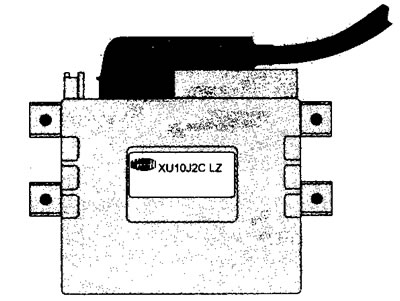
12.1 Electronic control unit Magneti Marelli 8P
Main functions of the electronic control unit (ECM)
DC voltage is supplied from the battery to contact pin No. 4 of the electronic control unit. The connection is made via a 15-pin contact relay. When the ignition is on, power is supplied to the main relay, which in turn supplies switching voltage to pin #35 of the electronic control unit. Now power from pin #35 is supplied to the electronic control unit.
Most sensors, such as the intake air Temperature sensor (ATS), the coolant temperature sensor (CTS), the throttle position sensor (TPS), and the intake manifold absolute air pressure sensor (IDP) now receive a voltage of 5.0 Volts from the corresponding contact pin of the electronic control unit. When the engine is cranking or running, the signal from the crankshaft angle sensor (CAS) causes the ECU to ground pin #23 so that the fuel pump starts to operate. Ignition and fuel injection functions are also activated. All drives (ignition coil, injector, carbon filter solenoid valve, etc.) are supplied with nominal battery voltage through the fuel pump relay, and the electronic control unit closes the circuit.
Reference voltage
The initial voltage level supplied from the ECU to many sensors is 5.0 volts.
Electronic Control Module (ECM) Power Supplies and Ground Checks
Nominal battery voltage (nbv)
| State | Volts |
| The ignition is on | 11.5-13.5 |
| When turning the crankshaft | 8.0 + |
| With the engine running | 13.0-15.9 |
Electronic Control Module (ECM) voltage values
Terminal numbers
| ECM | Element | State | Volts |
| 4 | Battery: t30 (via the fuel injection relay) | The ignition is off | nbv |
| 35 | Relay output terminal | The ignition is on | nbv |
| 4 | Relay control circuit | The ignition is off | nbv |
| 4 | Relay control circuit | The ignition is on | 1.25 (max) |
| 23 | Relay control circuit | The ignition is on | nbv |
| 23 | Relay control circuit | When cranking the crankshaft/the engine is running | 1.25 (max) |
| 14, 34 | ECM grounding | The ignition is on | 0.25 (max) |
Note: nbv is the nominal battery voltage (see illustration 12.2)
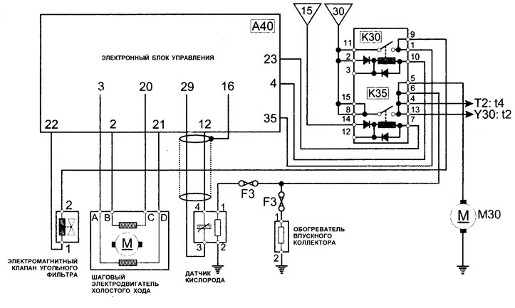
12.2 ECM/ISSM/CFSV/OS/FP/IMH/Relay Wiring Diagram
Checking the ECM electronic control unit (general check)
1. Inspect the ECU multi-pin connector for signs of corrosion or damage.
2. Make sure the connector terminal pins are properly installed and have good contact with the ECU multi-pin connector.
Voltage values at electronic control unit (ECM) connections
Note. Contact pins No. 17 and No. 34 are the grounding of the electronic control unit for the MM 8R engine control system. For this reason, if possible, contact pins #17 or # 34 should be used to connect a voltmeter or oscilloscope.
ECM Pin No. 4
Note 1. Pin #4 is connected to the battery (+) terminal via the fuel injection relay so voltage is available when the ignition is off.
Note 2. When measuring voltage on a multi-pin connector, remember that the terminals are in reverse order. The multi-pin connector remains connected to the component and the insulation of the ECU multi-pin connector should be folded back. The positive probe of the voltmeter is attached to the corresponding contact pin.
The electronic control unit is connected
1. Connect the positive lead of the voltmeter to pin #4. The voltmeter should indicate the battery's nominal voltage (see note 2).
The electronic control unit is disconnected
2. Attach the negative probe of the voltmeter to the ground contact pin of the ECU.
3. Attach the positive probe of the voltmeter to contact pin #4. The voltmeter should indicate the nominal voltage of the battery.
ECM Pin 35
Note: ECU pin #35 is connected to the main relay output terminal and voltage must be available when the ignition is on.
The electronic control unit is connected
1. The ignition is on.
2. Connect the positive lead of the voltmeter to pin #35. The voltmeter should indicate the nominal voltage of the battery (see note 2).
The electronic control unit is disconnected
3. The ignition is on.
4. Attach the negative probe of the voltmeter to the ground on the ECU.
5. Connect the positive probe of the voltmeter to pin #35. The voltmeter should indicate the nominal voltage of the battery.
ECM Pin 4 (main control circuit of the relay)
The relay and electronic control unit are connected
1. Ignition is off.
2. Connect the positive probe of the voltmeter to contact pin #4, the device should show the nominal voltage of the battery (see note 2).
3. If there is no voltage, check the relay and relay wiring.
4. The ignition is on. The voltage should drop to almost zero.
5. If not, disconnect the ECU multi-pin connector and connect a temporary jumper wire from pin #4 to ground.
6. The relay is working: Check the voltage supply to the electronic control unit and its grounding. If the wiring is OK, then the Electronic Control Module (ECM) may be faulty.
7 Relay not working: Check relay and relay wiring.
ECM Pin 23 (fuel pump relay control circuit)
(Original publication on the website: peugeotbook.ru)
The relay and electronic control unit are connected
1. Before starting this test, check the functionality of contact pin #23.
2. The ignition is on.
3. Connect the positive probe of the voltmeter to contact pin #23, the device should show the nominal voltage of the battery (see note 2).
4. If there is no voltage, check the relay and relay wiring.
5. Turn the crankshaft or start the engine, the voltage should drop to almost zero.
6. If not, disconnect the ECU multi-pin connector and connect a temporary jumper wire from pin #23 to ground.
7. The relay is working: Check the voltage supply to the electronic control unit and its grounding. If the wiring is OK, then the Electronic Control Module (ECM) may be faulty.
8. Relay does not work: Check the relay and relay wiring.
ECM ground pins #17 and #34
The electronic control unit multi-pin connector is connected
1. The ignition is on.
2. Attach the negative probe of the voltmeter to the ground on the engine.
3. Attach the positive probe of the voltmeter to the ground terminal, the voltmeter should indicate 0.25 volts (maximum).
The electronic control unit multi-pin connector is disconnected
1. Ignition is on or off.
2. Attach the negative probe of the voltmeter to the ground terminal.
3. Attach the positive probe to the #4 terminal of the ECU, the voltmeter should indicate the nominal voltage of the battery if the grounding meets the specifications.
Shielded wire signal
To reduce radio frequency interference (RFI) on some sensors (i.e. CAS, KS and OS) a shielded wire is installed. The shielded wire for the crankshaft angle sensor is connected to terminal #17 of the ECU main ground wire to reduce interference to a minimum. The other shielded wires are connected to the ground pin #34 of the ECU.
Self-diagnosis function
The MM 8P system has a serial port for diagnostics and system configuration. Thanks to the self-diagnosis function, some parameters can be changed (i.e. the CO value on models not equipped with a catalytic converter, or the ignition timing).
In addition, the system has a self-testing capability, which consists of continuously evaluating signals received from sensors and, if a malfunction is detected, entering a corresponding code into a specially allocated memory. An appropriate Fault Code Reader (FCR) can retrieve this code from the MM 8P serial port (see illustration 12.3). If a fault is detected, the code will remain stored until it is cleared from the memory using an appropriate fault code reader.
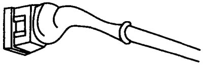
12.3 Self-diagnosis electrical connector (SD)
If the electronic control module (ECM) detects a malfunction, it grounds pin #6, and the malfunction indicator lamp (MIL) illuminates on the instrument cluster. The lamp remains illuminated until the malfunction is corrected. However, if the fault is minor, the warning lamp will not light, although the electronic control unit will register a fault code. A fault code will be recorded under these circumstances, and the presence of the fault code indicates that a fault has been detected in the relevant section of the circuit.
In addition to the self-test function, the MM 8P has a special device (LOS is a mode that allows you to get to the nearest workshop). If one or more sensors fail, the electronic engine management system will detect a fault instead of the faulty sensor. In LOS mode, the engine will continue to run, albeit inefficiently. However, a faulty crankshaft angle sensor will, of course, stop the engine completely.
This means that the engine may run reasonably well if the fault is in one or more auxiliary sensors. If a major sensor, such as the Manifold Absolute Pressure (MAP) sensor, is damaged, the vehicle's handling performance will be reduced.
A fault detected by the self-diagnosis function remains in the computer memory until the fault code is cleared from the memory by the appropriate device or when the battery is disconnected.
Adaptive memory
Over a period of time, the electronic control unit will "remember" the optimal idle speed for a specific engine - regardless of its age, engine condition and engine load - so that the correct idle speed is always maintained. Adaptive idle settings are stored in memory.
Adaptive dimensions and fault codes stored in memory will be lost when the battery is removed from the vehicle. This means that idle quality will deteriorate until the electronic control unit relearns its optimal settings.