



Table of contents: Voltage and resistance values of the…🠇 Type of sensors 🠇 Influence of external factors 🠇 Checking sensors (general check) 🠇 Checking the performance of sensors…🠇 Checking the intake air temperature…🠇 Engine Running Tests (CTS) 🠇 Zero volts at the signal wire…🠇 5.0 Volts at the signal wire terminal 🠇 The signal voltage or supply voltage…🠇 Testing resistance using an ohmmeter 🠇 The coolant temperature sensor is…🠇 The coolant temperature sensor has…🠇
Intake air temperature sensor (ATS) (see illustration 12.10) located in the intake manifold, where it measures the temperature of the air sucked into the engine. The signal from the ATS sensor makes it possible to more accurately determine the volume of air sucked into the engine. This signal is approximately 2.0 to 3.0 volts at an outside temperature of 20°C, decreasing to approximately 1.5 volts when the temperature rises to approximately 40°C.
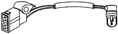
12.10 Intake Air Temperature Sensor (ATS)
The coolant temperature sensor (CTS) is located in the cooling system and measures the temperature of the engine coolant.
Both sensors have a negative temperature coefficient (NTC).
Voltage and resistance values of the intake air temperature sensor and the coolant temperature sensor
Terminal numbers
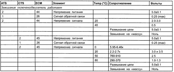
See illustration 12.11
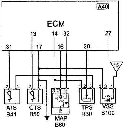
12.11 ATS/CTS/MAP/TPS/VSS Wiring Diagram
Type of sensors
Both sensors have a negative temperature coefficient (NTC)
Note: The intake air temperature sensor has little effect on engine operation.
Influence of external factors
- Vacuum leak
- Cooling system malfunction
- Low oil level
Checking sensors (general check)
1. If you suspect that any of the sensors is faulty, you must perform the following checks.
2. Inspect the multi-pin connector for signs of corrosion or damage.
3. Make sure the connector terminal pins are properly installed and have good contact with the multi-pin connector.
Checking the performance of sensors with an oscilloscope or voltmeter
1. Bend back the rubber insulation to the multi-pin connectors (where possible) or connect the output block (OB) between the ECU multi-pin connector and the ECU.
2. Connect the negative probe of the oscilloscope or voltmeter to ground on the engine OR to ground on the sensor.
3. Connect the positive probe of the oscilloscope or voltmeter to the signal wire terminal of the sensor.
4. The engine is not running, the ignition is on.
Checking the intake air temperature sensor (ATS)
1. The signal voltage will change according to the intake air temperature or coolant temperature. See the diagram showing voltages at different temperatures.
2. When testing at different temperatures, the intake air temperature sensor (ATS) can be heated with a hair dryer or cooled with something like "Freezit," a cooling aerosol spray available at electrical supply stores. When the ATS is heated or cooled, the temperature changes, thereby changing the resistance and voltage accordingly.
3. If the intake air temperature sensor signal voltage is zero (open circuit or short to ground) or 5.0 volts (ATS - circuit breaker), then perform the appropriate checks described below.
Engine Running Tests (CTS)
1. Let the engine cool down.
2. The engine is not running, the ignition is on.
3. The signal voltage will change according to the temperature. See the coolant temperature sensor diagram for voltages at various temperatures.
4. Make sure the coolant temperature sensor voltage matches the coolant temperature sensor temperature.
5. Start the engine and allow it to warm up to normal operating temperature. When the engine is warm, the voltage should drop in accordance with the coolant temperature sensor diagram.
6. The main problem is that the coolant temperature sensor (CTS) resistance readings (and voltage) fall outside normal ranges.
The coolant temperature sensor voltage can typically be between 3.0 and 3.5 V on a cold engine and between 1.0 and 1.3 V on a warm engine. If the voltage fluctuates between 1.75 V on a cold engine and 1.25 V on a warm engine, the engine will be difficult to start from a cold state, and the operation of a warm engine with a too rich fuel mixture will be difficult.
- The self-diagnosis system will not generate a fault code because the coolant temperature sensor is still operating within its design parameters. 7 If the coolant temperature sensor signal voltage is zero (open circuit or short to ground) or 5.0 volts (CTS - circuit breaker), then perform the appropriate checks described below
Zero volts at the signal wire terminal
1. Check if the signal wire is shorted to ground.
2. Check for continuity of the signal wire between the sensor and the electronic control unit.
3. If the coolant temperature sensor wiring is OK, check the power and ground contacts of the electronic control unit. If the contacts are OK, then the electronic control unit may be faulty.
Source of the article is posted at (PeugeotBook)
5.0 Volts at the signal wire terminal
1. This voltage indicates that the circuit is open. This may be caused by the following:
2. The signal wire terminal in the sensor multi-pin connector has poor contact with the sensor.
3. Open circuit of the sensor or sensor signal wire.
4. Break in the grounding part of the sensor circuit.
The signal voltage or supply voltage matches the battery voltage
- Check for a short in the wire connected to the positive (+) battery terminal or the sensor supply circuit.
Testing resistance using an ohmmeter
Intake air temperature sensor
- The resistance determination test can be performed at different temperatures as well as with a comparison made to a temperature/resistance chart. Learn about the voltage test using the coolant temperature sensor heating/cooling method.
The coolant temperature sensor is installed on the vehicle
- The resistance determination test can be performed at different temperatures as well as with a comparison made to a temperature/resistance chart. When the resistance is within the specified parameters for a cold engine (20°C), the coolant temperature should be within ±5°C of this figure.
Note: If the temperature was measured during testing by applying a thermometer to the outside of the coolant passage or coolant temperature sensor, it must be taken into account that the actual coolant temperature may be slightly higher than the surface temperature of the coolant temperature sensor.
The coolant temperature sensor has been removed from the vehicle
1. The recommended method involves removing the coolant temperature sensor from the vehicle.
2. Place the sensor in a suitable container of water and measure the water temperature.
3. Measure the resistance of the coolant temperature sensor and check the resistance according to the table.
4. Heat the water, periodically measuring the water temperature and the resistance of the coolant temperature sensor, and compare the resistance values with the data given in the table.