



Table of contents: Ignition coil 🠇 Static ignition system 🠇 Voltage values in the primary…🠇 Checking the primary winding of the…🠇 Checks with the engine off 🠇 Oscilloscope 🠇 Checks on a running engine 🠇 Checking the electronic control unit 🠇
Ignition coil
Ignition coils use low resistance on the primary winding of the ignition coil to increase the current in the primary winding and the primary energy. The amplifier limits the current in the primary winding to approximately 8 A in order to accumulate the necessary energy reserve to create a spark discharge.
Static ignition system
Although the ignition system is called a static ignition system, its basic functions are the same as on models equipped with a conventional contactless ignition system. In static (without distributor) the Displacement Ignition System (DIS), or so-called "wasted spark system," uses two ignition coils to create a spark discharge on two spark plugs simultaneously (see illustration 12.8).
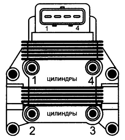
12.8 Ignition coil of the static ignition system (DIS)
One cylinder creates a spark discharge on the compression stroke, and the paired cylinder does so on the exhaust stroke, where the spark does not perform any useful function, i.e. is "idle".
Therefore, two pairs of ignition coils are required for a 4-cylinder engine. Approximately 3 kV is still required to create a "wasted spark." Each ignition coil receives voltage from the ignition switch and from a separate wire running to the electronic control unit. In this way, the electronic control unit can activate each ignition coil individually.
Voltage values in the primary winding of the ignition coil
Note: Voltage is supplied by the fuel pump relay and is only available for approximately one second after the ignition is turned on - either when cranking or with the engine running. Bypassing the relay provides the voltage required for testing when the engine is off.
Terminal numbers
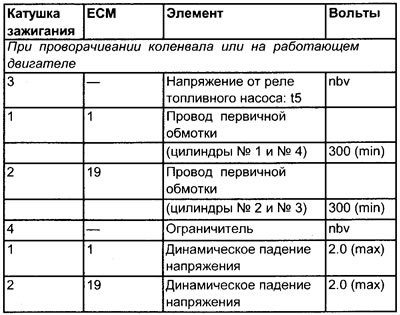
See Figure 12.6
Checking the primary winding of the ignition coil (general check)
1. Check the reliability of the ignition coil terminal connections.
2. Clean any accumulated dirt and deposits from the ignition coil assembly using an aerosol cleaner. The remaining dirt promotes the formation of new dirt, which often leads to leakage currents.
3. Inspect the ignition coil for excessive leakage (current), especially around the coil post.
4. Connect the negative probe of the oscilloscope or breaker duration meter to ground on the engine.
5. Connect the positive probe of an oscilloscope or a breaker duration meter to the negative (-) terminal of one of the two ignition coils #1 or #2.
6. After checking one terminal of the ignition coil, check the other terminal.
Checks with the engine off
1. Turn the crankshaft.
2. Either the primary winding waveform or the duty cycle reading must be obtained. If the device can measure readings in milliseconds, then this is the most successful measurement.
Oscilloscope
In addition to a clear waveform, the peak voltage values in the primary winding should be at least 300 volts.
3. Clear primary waveform or sufficient signal:
- The primary winding of the ignition coil (including the crankshaft angle sensor (CAS)) provides a sufficient signal.
- The fault is not related to the low voltage circuit of the ignition system.
4. Primary waveform is unclear or signal is weak:
- Check the signal from the crankshaft angle sensor.
5. Connect the positive probe of the oscilloscope or voltmeter to the terminals of ignition coil No. 3.
6. Turn the crankshaft and check for voltage at the positive (+) terminal of ignition coil No. 3.
7. If there is no voltage, trace the wiring back to the relay power terminal.
8. Check for voltage at the negative (-) terminals of ignition coils No. 1 and No. 2.
9. If there is no voltage, disconnect the wire from the (-) terminal of the ignition coil and check again.
10. If there is still no voltage, check the resistance on the primary winding of the ignition coil.
11. The voltage corresponds to the nominal voltage of the battery, check the short circuit to ground between the corresponding terminal of the ignition coil and the contact pin of the electronic control unit.
12. Disconnect the multi-pin connector of the electronic control unit and check for battery voltage at terminals No. 1 and No. 19 of the electronic control unit while cranking the crankshaft.
13. Weak or no voltage:
- Check for continuity between the ignition coil terminal and the ECU contact pin.
14. If the wiring is OK, check all power and ground contacts of the electronic control unit.
15. If the checks do not reveal any faults, then the electronic control unit may be faulty. However, before replacing the electronic control unit, the ignition coil being replaced should be checked.
Checks on a running engine
1. Perform the following tests on the primary terminal of ignition coil #1, and then in turn on coil #2. The results on each terminal should be very similar.
2. Connect an oscilloscope or a contact duration meter to the negative terminal of ignition coil No. 1.
3. Start the engine and let it idle and run at different speeds. Record the duty cycle, peak primary voltage, and dynamic voltage drop.
4. Compare the obtained results with the values given in the specifications. Please note that duty cycle readings vary between different vehicles of the same model. However, the readings in ms must be as accurate as possible.
5. It is important that as the engine speed increases, the duty cycle value as a percentage (%) increases.
6. It is important that as the engine speed increases, the duty cycle values in ms do not differ too much.
7. If the dynamic voltage drop is high (typically over 2.5 volts) in combination with a low peak voltage value in the primary winding and high pulse width % (in idle mode), then you should check the amplifier's functionality.
Warning. If the dynamic voltage drop is high (typically over 2.5 volts), but the peak voltage value in the primary winding and the pulse width % correspond to the norm, then the amplifier may be in good working order. Please remember that on this model the amplifier is an integral part of the ECU, so the readings will not improve if the ECU is replaced just because the dynamic voltage drop is too high.
Checking the electronic control unit
1. Check the ground contacts of the electronic control unit.
2. Make sure that wires from devices such as an RFI suppressor or alarm system are not connected to the primary (-) terminal of the ignition coil.
3. If the grounding and wiring are normal, and the peak value of the primary winding voltage and the pulse width % in idle mode are very high, then the electronic control unit is definitely faulty. Please read the warning above before replacing the ECU.
4. The results obtained at each terminal should be very similar.