



Table of contents: Setting the ignition timing 🠇 Amplifier 🠇 Crankshaft Angle Sensor (CAS) 🠇 Crankshaft Angle Sensor (CAS)…🠇 Crankshaft Angle Sensor (CAS)…🠇 Adjustment 🠇 Influence of external factors 🠇 Checking the crankshaft angle sensor…🠇 Checking the CAS output signal with…🠇 Checking the crankshaft angle sensor…🠇 Checking the crankshaft angle sensor…🠇 Checking the crankshaft angle sensor…🠇 Checking the resistance of the…🠇 Shielded Sensor Wire (CAS) 🠇
Setting the ignition timing
The ignition timing on models equipped with the MM 8P system cannot be adjusted in the usual way. However, it is possible to adjust the ignition timing curve using a suitable fault code reader (FCR). This task should not be taken lightly; rather, the engine condition and system functions should be checked and assessed before adjusting the ignition timing.
| Cylinder numbers | Cylinder firing order | Displayed lead |
| 4 | 1-3-4-2 | 10-8° |
Amplifier
The MM 8P system amplifier contains a circuit for switching the negative terminal of the ignition coil at the right moment to turn on the ignition system. The amplifier circuit is included in the electronic control unit. The microprocessor controls the duration of the closed state of the ignition switch contacts under all operating loads on the engine and under the voltage supplied from the battery. The amplifier located inside the electronic control unit has one drawback - if the amplifier fails, the entire electronic control unit must be replaced.
Crankshaft Angle Sensor (CAS)
The crankshaft angle sensor (CAS), which determines fuel injection time and ignition timing, is located near the flywheel (see illustration 12.5). The crankshaft angle sensor consists of an inductive magnet that emits a magnetic field. The flywheel includes a disc containing a set of steel pins installed at intervals. When the flywheel rotates, the pins also rotate in the magnetic field, and an AC voltage signal is sent to the electronic control unit to determine the rotation speed. The two missing pins (180°C apart) are the TDC reference mark and indicate the crankshaft position by changing the signal as the flywheel rotates. One missing pin indicates the TDC position for pistons of cylinders No. 1 and No. 4, and the other pin indicates the TDC position for pistons of cylinders No. 2 and No. 3.
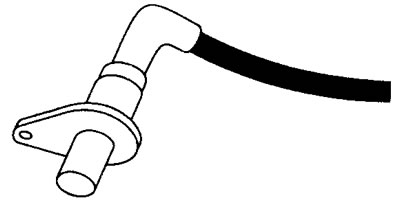
12.5 Crankshaft Angle Sensor (CAS)
Peak-to-peak voltage signal (if you look at the oscilloscope) the voltage can vary from 5 V at idle to over 100 V at 6000 rpm. The electronic control unit uses a digital converter to convert the AC pulse into a digital signal.
Crankshaft Angle Sensor (CAS) Voltage Values
Terminal numbers
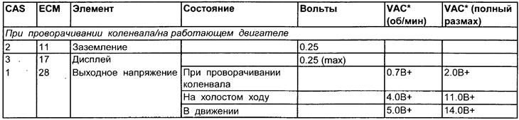
See Figure 12.6
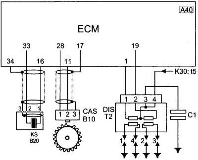
12.6 Electrical connection diagram of the primary winding of the ignition coil of the crankshaft angle sensor/knock sensor
Crankshaft Angle Sensor (CAS) Resistance Values
Terminal numbers
| CAS | ECM | Resistance (W) |
| 1 and 2 | 28 and 11 | 300 - 500 |
| 1 and grounding | 28 and 17 | Infinity |
| 2 and grounding | 11 and 17 | Infinity |
Adjustment
Air gap
Influence of external factors
- Incorrect air gap
- The flywheel is faulty or incorrectly installed
Checking the crankshaft angle sensor (CAS) (general check)
1. Inspect the crankshaft angle sensor multi-pin connector for signs of corrosion or damage.
2. Make sure the connector pins are properly installed and have good contact with the crankshaft angle sensor multi-pin connector.
3. Remove the crankshaft angle sensor from the engine block. Inspect the end face for signs of corrosion and damage.
4. Measure the resistance of the crankshaft angle sensor and compare the obtained value with the specifications. See resistance determination tests at the end of this chapter.
5. The presence of the faults listed above is a common cause indicating a defective sensor or a failure in the signal coming from the crankshaft angle sensor.
Checking the CAS output signal with an oscilloscope (when turning the crankshaft)
Note: This check should be performed with the engine off.
1. Disconnect the crankshaft angle sensor (CAS) or electronic control module (ECM) multi-pin connector.
2. Connect an oscilloscope between terminals 1 and 2 of the crankshaft angle sensor or the corresponding terminals of the ECM multi-pin connector.
3. Turn the crankshaft, the device should indicate a minimum voltage of approximately 4.0-5.0 V (full swing).
4. Check the uniformity of peak values. If one or more values are much lower than the others, this indicates damage to the crankshaft angle sensor cam.
5. If there is no signal or if the signal is very weak or unstable:
- Measure the resistance of the crankshaft angle sensor (CAS).
- Check the sensor for damage and contamination with dirt or oil.
- Check the flywheel for damage.
- Check the crankshaft angle sensor (CAS) air gap (if possible).
(Source of the article is website: «peugeotbook.ru»)
Checking the crankshaft angle sensor output signal with an oscilloscope
With the engine running
1. Connect the crankshaft angle sensor (CAS) or electronic control module (ECM) multi-pin connector and (where possible) bend back the insulation to obtain voltage by connecting the voltmeter probes to the crankshaft angle sensor terminals (or connect a terminal block (TB) between the ECU multi-pin connector and the ECU).
2. Best results are usually obtained by connecting the probes to the (+) terminal, although quite often a waveform can be obtained by connecting the probes to the ground terminal of the crankshaft angle sensor.
3. Run the engine at different speeds and check the stability of the signal (see illustration 12.7).
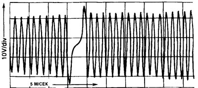
12.7 Typical Crankshaft Angle Sensor (CAS) Output Signal Waveform
Checking the crankshaft angle sensor output signal using an AC voltmeter (CAS)
When turning the crankshaft
Note: This check should be performed with the engine off.
1. Disconnect the crankshaft angle sensor (CAS) or electronic control module (ECM) multi-pin connector and connect an AC voltmeter between the CAS terminals.
2. Turn the crankshaft. The gauge should read approximately 0.7 V (rpm) minimum, although most good gauges will provide an output voltage of over 1.4 V (rpm).
Note: An AC voltmeter at least proves that the crankshaft angle sensor is producing a signal. However, AC voltage is an average voltage, so it does not accurately indicate damage to the crankshaft angle sensor cams.
Checking the crankshaft angle sensor output signal using an AC voltmeter (CAS)
With the engine running
Note: Measuring output voltage with the engine running will be a little tricky.
1. Connect the multi-pin connector and peel back the insulation (where possible), to obtain voltage by connecting the voltmeter probes to the sensor terminals.
2. Start the engine and let it idle. The alternating current (VAC) voltage (rpm) can be displayed at different engine speeds by adjusting the throttle valve.
Note: This is possible (even probably), that the engine will not start with the voltmeter connected. Alternatively, if the voltmeter is attached while the engine is running, it may stall or even misfire when the throttle valve opens.
3. First, start the engine at 2000 rpm, and then connect the voltmeter probes, the high output voltage at this speed is usually enough to prevent the engine from stalling and allow it to continue running. The engine will not be damaged if the specifications are followed when connecting the voltmeter.
Checking the resistance of the crankshaft angle sensor (CAS) using an ohmmeter
1. Disconnect the crankshaft angle sensor (CAS) or electronic control module (ECM) multi-pin connector and connect an ohmmeter between the two terminals leading to the sensor.
2. Record the obtained resistance and compare it with the resistance values of the crankshaft angle sensor (CAS).
Note: Even if the resistance meets the specifications, this does not prove that the crankshaft angle sensor can produce an acceptable signal.
Shielded Sensor Wire (CAS)
1. The crankshaft angle sensor (CAS) may have a shielded wire (not in all cases). Locate the multi-pin connector of the electrical wiring or disconnect the multi-pin connector of the electronic control module (ECM).
2. Place the ohmmeter probe on one of the sensor terminals No. 1 or No. 2.
3. Apply the other ohmmeter probe to the terminal of the shielded wire. The device should show infinite resistance.
4. Disconnect the ohmmeter probe from the shielded wire terminal and connect it to ground. The reading should also be infinity.
Note: On some systems, the crankshaft angle sensor shield wire is connected to the crankshaft angle sensor ground wire. In this case, the presence of conductivity will be registered by the ohmmeter, and this is normal for this vehicle. Refer to the wiring diagrams to determine which wires connect to the crankshaft angle sensor.