
English Русский
Български
Беларускі
Український
Српски
Hrvatski
Română
Polski
Slovenský
Magyar
Bookmark Articles Sitemap Contacts
Company Hyundai Company Opel Company Skoda Company Kia Company Mitsubishi Company LADA Company Audi
PeugeotBook.ru


Series 100   Series 200   Series 300   400-500   Series 600   Crossovers   Others
 
Partner I (1996-2008) Peugeot 807 (2002-2014) Peugeot 806 (1994-2002) Peugeot J5 (1981-1993)

General description (Peugeot Eurovans 806)

  • Main
  • Пежо
  • Peugeot 806 (1994-2002)
  • Power unit
  • ECM Bosch Motronic MP 3.2
  • General description
0
Table of contents: Main functions of the electronic…🠇 Reference voltage 🠇 Electronic Control Module (ECM)…🠇 Electronic Control Module (ECM)…🠇
The Bosch Motronic MP3.2 electronic engine management system (EMS), which has been used to control Citroen and Peugeot engines since around 1993, is an integrated system that controls the ignition coil primary winding, fuel delivery and idle speed adjustment via the same electronic control unit (ECM) (see illustration 11.1). MP3.2 is an improved version of MP3.1, in which the number of ECM contact pins has been increased from 35 to 55.
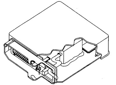
11.1 Electronic control unit Motronic MP3.2

11.1 Electronic control unit Motronic MP3.2


The electronic control unit (ECM) simultaneously determines the ignition timing and fuel injection duration. This way, the best ignition and fuel delivery timing is determined. The Bosch Motronic system uses the same fuel injection functions as the L-Jetronic system. A 55-pin multi-connector connects the electronic control unit to the battery, sensors, and actuators.

Main functions of the electronic control unit (ECM) (MPi)


DC voltage is supplied from the battery to contact pin No. 18 of the electronic control unit. This allows the self-diagnostic program to save data. When the ignition is on, the fuel injection system main relay supplies voltage to pin #37 of the ECU, as well as to the fuel injectors and the idle speed control valve (ISCV).


Most sensors (as opposed to those that produce voltage, for example: crankshaft angle sensor (CAS), oxygen sensor (OS)) now receive a voltage of 5.0 Volts from the corresponding contact pin of the electronic control unit. When the engine is cranking or running, the signal from the crankshaft angle sensor (CAS) causes the ECU to ground pin #3 so that the relay begins to supply voltage to the ignition coils and fuel pump. If cranking continues, the ECU will close each drive circuit by pulsing the appropriate ground wire, and the injectors, idle speed control valve (1SCV), ignition coils, and fuel pump will begin to operate.

(Original text is located at peugeotbook.ru)

Reference voltage


The initial voltage level supplied from the ECU to many sensors is 5.0 volts.

Electronic Control Module (ECM) Power Supplies and Ground Checks


Nominal battery voltage (nbv)


StateVolts
The ignition is on11.5-13.5
When turning the crankshaft8.0 +
With the engine running13.0-15.9

Electronic Control Module (ECM) voltage values


Terminal numbers


ECMElementStateVolts
18Battery: t30The ignition is offnbv
37Relay output terminalThe ignition is onnbv
36Relay control circuitThe ignition is offnbv
36Relay control circuitThe ignition is on1.25 (maximum)
3Relay control circuitThe ignition is onnbv
3Relay control circuitWhen cranking the crankshaft/the engine is running1.25 (maximum)
14, 19, 24 and 47ECM groundingThe ignition is on0.25 (maximum)

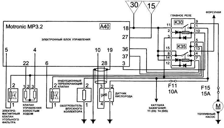
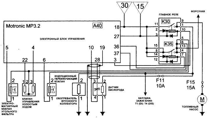
Note: nbv is the nominal voltage of the battery (see illustrations 11.2, 11.3, 11.4, 11.5, 11.6)
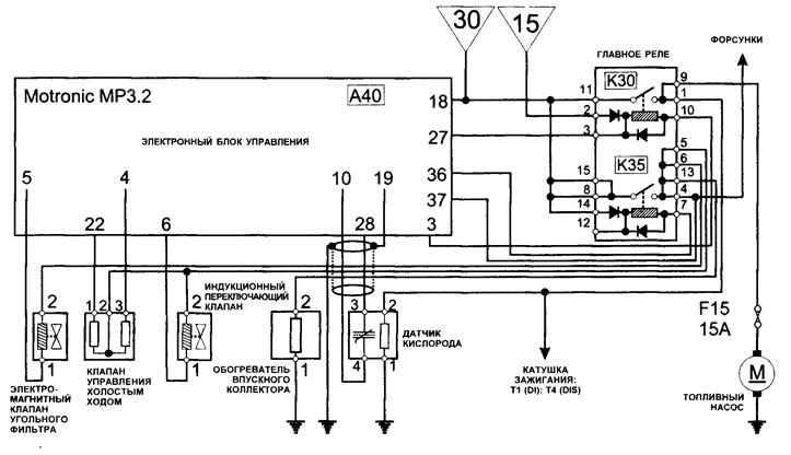


11.2 ECM/OS/ISCV/CFSV/ICOV/IMH/Relay/Wiring Diagram (306)
11.2 ECM/OS/ISCV/CFSV/ICOV/IMH/Relay/Wiring Diagram (306)


11.3 ECM/OS/ISCV/CFSV/ICOV/IMH/Pene/ Wiring Diagram (405 - early models)
11.3 ECM/OS/ISCV/CFSV/ICOV/IMH/Pene/ Wiring Diagram (405 - early models)


11.4 ECM/OS/ISCV/CFSV/ICOV/IMH/Relay/Wiring Diagram (405 - late models)
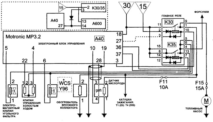
11.4 ECM/OS/ISCV/CFSV/ICOV/IMH/Relay/Wiring Diagram (405 - late models)


11.5 ECM/OS/ISCV/CFSV/ICOV/WCS/IMH/Relay/Wiring Diagram (605/XM)
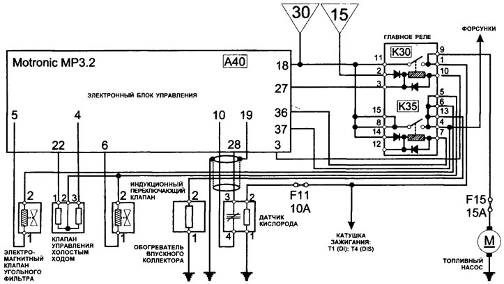
11.5 ECM/OS/ISCV/CFSV/ICOV/WCS/IMH/Relay/Wiring Diagram (605/XM)


11.6 ECM/OS/ISCV/CFSV/ICOV/IMH/Relay/Wiring Diagram (Xantia/ZX)

11.6 ECM/OS/ISCV/CFSV/ICOV/IMH/Relay/Wiring Diagram (Xantia/ZX)
This article is available at russian, bulgarian, belarusian, ukrainian, serbian, croatian, romanian, polish, slovak, hungarian
Article reviewed by editor: Shirokov Arseny
Share information:
Previous
Peugeot 806: ECM Bosch Motronic MP 3.2
Next

 
Checking the electronic control unit ECM (general check)
Self-diagnosis function
Ignition systems
Crankshaft Angle Sensor (CAS)
Camshaft position sensor (CMP)
See similar information for other Peugeot models

➨ General information Peugeot 106 (1991-2003)
➨ General information about the ignition system of the TU5 petrol… Peugeot 207 (2006-2014)
➨ General description of the Peugeot 305 Peugeot 305 (1977-1989)
➨ Catalyst — General Information Peugeot 405 (1987-1997)
➨ Keys — General Information Peugeot 605 (1989-2000)
Link to this article in different formats
Comments and feedback from visitors
No comments yet


Add two numbers 47 + 42


Partner I (1996-2008) 
  • General information
  • Introduction to the guide
  • Faults en route
  • Weekly checks
  • User manual
  • Maintenance (petrol)
  • Maintenance (diesel)
  • Power unit
  • Petrol engines
  • Diesel engines «XUD»
  • Diesel engines «DW»
  • Overhaul of petrol engines
  • Overhaul of diesel engines
  • Cooling and heating
  • Power and exhaust (petrol)
  • Power and exhaust (XUD diesels)
  • Power and exhaust (DW diesels)
  • Emission reduction
  • Starting and charging system
  • Transmission
  • Clutch
  • Mechanical gearbox
  • Drive shafts
  • Chassis, running gear
  • Brake system
  • Car suspension
  • Steering
  • Body and interior
  • Exterior (external elements)
  • Interior (internal elements)
  • Doors, locks and windows
  • Electrical equipment
  • Equipment and devices
  • Electrical circuits
Peugeot 807 (2002-2014) 
  • General information
  • Operating instructions
  • Maintenance
  • Troubleshooting
  • Power unit
  • Gasoline engines
  • Diesel engines
  • Cooling and heating
  • Fuel injection (petrol)
  • Fuel system (diesel)
  • Fuel system
  • Exhaust system
  • Ignition system
  • Transmission
  • Clutch
  • Manual gearbox
  • Automatic gearbox
  • Chassis, running gear
  • Brake system
  • Car suspension
  • Steering system
  • Body and interior
  • Exterior (external elements)
  • Interior (internal elements)
  • Electrical equipment
  • Power devices
  • Electrical circuits
Peugeot 806 (1994-2002) 
  • General information
  • User manual
  • Maintenance
  • Power unit
  • Petrol engines
  • Diesel engines
  • Lubrication system
  • Cooling system
  • Fuel injection (petrol)
  • Fuel system (diesel)
  • Ignition and exhaust systems
  • ECM Bosch Motronic MP 3.2
  • ECM Magneti-Marelli (MM)
  • Transmission
  • Clutch
  • Mechanical gearbox
  • Chassis, running gear
  • Brake system
  • Car suspension
  • Steering
  • Electrical equipment
  • Equipment and devices
  • Electrical circuits
Peugeot J5 (1981-1993) 
  • General information
  • Introduction to manual
  • Specifications
  • Gasoline engine
  • Engine repair
  • Lubrication system
  • Cooling system
  • Fuel system
  • Ignition system
  • Diesel engine
  • Engine repair (DB9)
  • Lubrication system (DB9)
  • Cooling system (DB9)
  • Fuel injection (DB9)
  • Engine repair (U25)
  • Lubrication system (U25)
  • Cooling system (U25)
  • Fuel injection (U25)
  • Transmission
  • Clutch
  • Gearbox
  • Drive shafts
  • Chassis, running gear
  • Steering system
  • Car suspension
  • Brake system
  • Electrical equipment
  • Power devices
  • Electrical circuits
PeugeotBook.ru © 2018–2026 | Mobile version | Sitemap: EN BG BY UA RS HR RO PL SK HU | Write message | Site search | Add to bookmarks | Peugeot owners
106 (1991-2003) | 206 (1998-2012) | 207 (2006-2014) | 305 (1977-1989) | 306 (1993-2002) | 307 (2001-2008) | 405 (1987-1997) | 406 (1995-2004) | 605 (1989-2000) | Partner-I (1996-2008) | Eurovans-807 (2002-2014) | Eurovans-806 (1994-2002) | J5 (1981-1993) |
Cookies are used to ensure the correct display of pages on the site.