



Table of contents: Camshaft position sensor (CMP)…🠇 Checking the camshaft position…🠇 Checking the operability of the…🠇 Checking the output signal of the…🠇 No signal or signal is unstable,…🠇 Lack of tension 🠇
The camshaft position sensor (CMP) detects the position of piston #1 in its cylinder to provide sequential fuel injection signals to each cylinder. In MP3.2 system, this sensor is a Hall sensor to produce a signal. Camshaft position sensor (CMP) (see illustration 11.13) located next to cylinder No. 1. When the piston of cylinder No. 1 is in the TDC position, the pin is located opposite the camshaft position sensor on the intake camshaft. Voltage is supplied to the Hall sensor from the main relay, and the sensor is grounded by the crankshaft angle sensor feedback signal. The third wire is connected to the Bosch Motronic electronic control unit. When the crankshaft rotates, the pin on the camshaft passes under the sensor, returning a signal to the electronic control unit, which indicates the piston position of cylinder #1. Once the electronic control unit has recognized the piston position of cylinder #1, the correct ignition timing and fuel injection into each individual cylinder can be determined at the right moment.
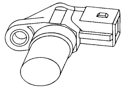
11.13 Camshaft Position Sensor (CMP) (hall sensor)
Camshaft position sensor (CMP) voltage values
Terminal numbers
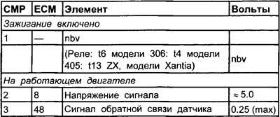
See illustration 11.10, 11.11
Checking the camshaft position sensor (CMP) (general check)
1. Inspect the camshaft position sensor multi-pin connector for signs of corrosion or damage.
2. Make sure the connector pins are properly installed and have good contact with the camshaft position sensor multi-pin connector.
Checking the operability of the camshaft position sensor (CMP)
1. The test is quite simple. The sensor has three wires: a power wire, a ground wire, and a signal wire.
2. Connect the positive probe of the voltmeter to the multi-pin connector of the camshaft position sensor (see note 2) or connect the output block (OB) between the ECU multi-pin connector and the ECU.
3. Connect the negative probe of an oscilloscope, breaker duration meter, or voltmeter to ground on the engine.
4. Connect the positive probe of an oscilloscope, contact duration meter, or voltmeter to the camshaft position sensor signal wire terminal.
Checking the output signal of the camshaft position sensor (CMP)
- Start the engine and let it idle and check the output signal (see illustration 11.14)
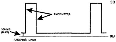
11.14 Typical waveform of the camshaft position sensor (CMP) output signal
No signal or signal is unstable, duty cycle or voltage
1. The camshaft position sensor multi-pin connector is disconnected and the ignition is on.
2. Check the voltage supply to the power wire terminal of the camshaft position sensor (CMP).
3. Check that the camshaft position sensor ground wire terminal is seated firmly at the ground point.
4. Connect the positive probe of the voltmeter to the signal wire terminal.
5. The device should show a voltage of approximately 5.0 volts.
Lack of tension
1. Check for voltage at the multi-pin connector terminal of the electronic control unit.
2. If there is voltage in the electronic control unit, check the conductivity of the signal wire.
3. If there is no voltage in the electronic control unit, check the voltage supply to the electronic control unit and its grounding. If the power supply and ground are OK, then the electronic control unit may be faulty.