



Table of contents: Knock sensor (KS) voltage values 🠇 Knock sensor frequency 🠇 Influence of external factors 🠇 Checking the knock sensor (general…🠇 Knock sensor testing procedure 🠇 Knock sensor testing procedure…🠇
Since detonation can occur at different times in each individual cylinder, the Bosch Motronic MP3.2 uses a knock control unit - KCU (in the electronic control unit), to indicate the specific cylinder or cylinders in which detonation occurs. The knock sensor is installed on the cylinder block. The sensor converts the signal into a voltage signal (see illustration 11.23), returning to the detonation control unit for evaluation and replay of the action. The detonation frequency is in the 15 kHz frequency range.
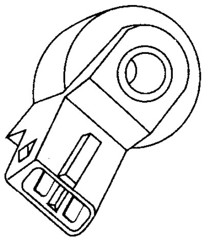
11.23 Knock sensor (KS)
Knock sensor (KS) voltage values
Terminal numbers
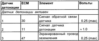
See Figure 11.24
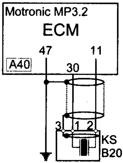
11.24 Electrical connection diagram of the KS knock sensor
Note: The knock sensor signal will provide a maximum voltage amplitude of approximately 1.0 volts.
Knock sensor frequency
Approximately 15 kHz.
Influence of external factors
- Incorrect setting of the main ignition timing angle
- Low quality gasoline
- Ignition system malfunction
- Cooling system malfunction
- Formation of carbon deposits in cylinders
Checking the knock sensor (general check)
1. Inspect the knock sensor multi-pin connector for signs of corrosion or damage.
2. Make sure the connector terminal pins are properly installed and have good contact with the knock sensor multi-pin connector.
Knock sensor testing procedure
Note: If the engine does not have timing marks, the piston of cylinder #1 must be set to the TDC position and the corresponding marking must be made on the housing and front pulley in order to perform the following procedure.
1. Connect the inductive timing light probe to the high tension wire of cylinder No. 1.
2. Let the engine idle.
3. Gently tap the engine block in the area of cylinder No. 1.
4. The ignition timing should be noticeably delayed.
5. Move the inductive stroboscope probe to cylinder No. 4.
6. Gently tap the engine block in the area of cylinder No. 4.
7. The ignition timing should be noticeably delayed.
Knock sensor testing procedure (Oscilloscope)
1. Connect the low voltage probe of the oscilloscope to terminal No. 2 of the knock sensor signal wire.
2. Gently tap the engine block in the area of one of the cylinders.
[Original publication on the website PeugeotBook]
3. The oscilloscope should display the waveform of the knock sensor signal (see illustration 11.25)
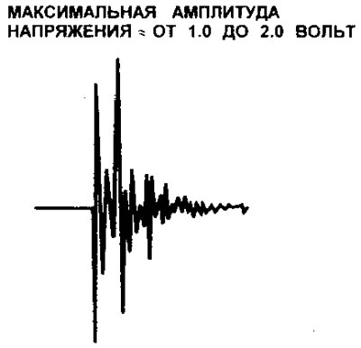
11.25 Typical waveform of the output signal of the KS knock sensor
4. Repeat the procedure for other cylinders.