



Table of contents: DIS amplifier voltage values 🠇 DI amplifier voltage values…🠇
Ignition amplifier (see illustration 11.15) includes a circuit to connect the negative terminal of the ignition coil to create a spark discharge. Depending on the model, the ignition system uses either one or two separate amplifiers. The electronic control unit (ECM) calculates the ignition timing and injection timing based on data received from the sensors.
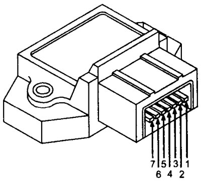
11.15 Ignition amplifier
For the static ignition system (DIS), two signals are sent in the required sequence to the amplifier, which then sends voltage to the corresponding negative terminal of the DIS ignition coil.
For direct ignition (DI), the ECU sends four signals, two signals to each amplifier, to apply voltage to the negative terminal of the ignition coil of the corresponding cylinder. Each booster is turned on twice during the engine cycle, and each booster also turns on two ignition coils. Amplifier A turns on ignition coils #2 and #4, and then amplifier B turns on ignition coils #1 and #3.
DIS amplifier voltage values
Terminal numbers

Note: nbv is the nominal voltage of the battery (see illustration 11.10)
DI amplifier voltage values (Amplifiers A and B)
Terminal numbers
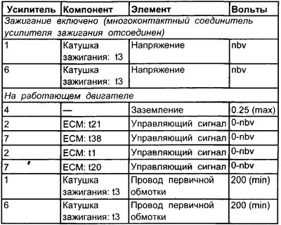
See illustration 11.11
Influence of external factors
- Ignition system malfunction
- The ignition switch is faulty
- Generator
- Voltage regulator or ignition distributor
Original is contained on the portal (PEUGEOTBOOK)