
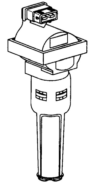
11.19 Ignition coils of the direct ignition system
The ignition timing setting is not adjustable on models equipped with Bosch Motronic MP3.2.
Voltage values on the primary winding of the ignition coil
Terminal numbers
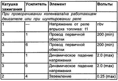
See illustration 11.11
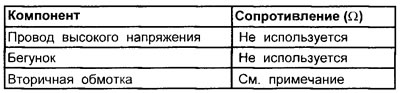
Resistance values on the primary winding of the ignition coil
Terminal numbers
| Ignition coil | Element | Resistance (Q) |
| 1 and 3 | Primary resistance | 0,65 |
| 15 and 2 | Secondary winding resistance | See note |
Note. The secondary circuit of the ignition coil is connected in series with the diode, so resistance or continuity cannot be tested.
Ignition Coil Primary Duty Cycle Table
| RPM | duty cycle % | msec (ms) |
| When turning the crankshaft | 15-30 | 15.0-20.0 |
| 1000 | 5-20 | 4.0-6.0 |
| 2000 | 25-35 | 4.0-6.0 |
| 3000 | 30-40 | 4.0-6.0 |
Checking the primary winding of the ignition coil (general check)
1. This static ignition system includes twin amplifiers and four ignition coils (one per spark plug).
2. The ignition test for each cylinder is individual.
3. Remove the eight screws and remove the ignition coil cover and remove the spark plugs.
4. Check up reliability of connection of all four plugs of the multicontact connector of the coil of ignition.
5. Unscrew the round multi-pin connector in the wiring harness at the rear of the cylinder head and check that the wire connectors are securely connected to the ignition coils.
Checks with the engine off
- Connect the negative lead of an oscilloscope or breaker closed time meter to ground on the motor.
Note. The following check is similar for both ignition coils of both ignition amplifiers. If necessary, booster A or B and ignition coils No. 1, 2, 3, or 4 should be replaced according to the test procedure described. Amplifier A controls ignition coils 4 and 2, amplifier B controls ignition coils 1 and 3.
Check booster A or B, ignition coils #1, #2, #3, or #4
Ignition Coil Primary Tests: Amplifier A or B, Ignition Coils #1, #2, #3, or #4
1. Bend the insulation to amplifier A or B and connect the positive probe of an oscilloscope or a breaker-contact meter to terminals #1 or #6.
2. Turn the crankshaft.
3. The instrument should show either the primary waveform or duty cycle reading. If the device can measure readings in milliseconds, then this is the most successful measurement.
Oscilloscope
In addition to a clear waveform, the peak voltage value in the primary winding must be at least 300 volts (see illustration 5.17)
4. A peak value less than 300V may be due to a malfunction of the primary windings of the ignition coils.
5. Clear primary waveform or sufficient signal: Ignition coil primary (including crank angle sensor (CAS)) gives a sufficient signal. The fault is not related to the low voltage circuit of the ignition system. However, if there is no ignition coil secondary output, the ignition coil may still be faulty.
Fuzzy primary waveform or insufficient signal
6. Check the signal from the crankshaft angle sensor (CAS).
7. Since voltage is supplied to the ignition coils only when the crankshaft is cranked and the engine is running, it is necessary to bypass the relay to check.
8. Turn off the ignition.
9. Disconnect the multicontact connector from the ignition booster.
10. Check amplifier #1 for nominal battery voltage. If voltage is present, the ignition coil circuit is OK.
No voltage at terminal No. 1 of the ignition coil
11. Bend the insulation of the ignition coil and check the voltage supply to the negative terminal No. 3 on the ignition coil 4.
12. If voltage is now present, check the continuity of the wire from the booster to the ignition coil.
13. If there is still no voltage, check the voltage supply to the positive terminal No. 1 on the ignition coil No. 4.
14. If the voltage is now present, check the resistance on the primary winding of the ignition coil.
15. If there is still no voltage, check the voltage supply from the fuel injection relay.
Control signal checks - amplifiers A and B
10. Bend the insulation to amplifier A or B and connect the positive probe of an oscilloscope or a breaker closed duration meter to terminal No. 2.
Note. When output block is available (WWII) Tests can be performed by connecting the output unit to the ECU pins.
11. Turn the crankshaft. The instrument will display the control signal as a square wave (see illustration 11.18) or duty cycle indication.
12. Connect the positive probe of the oscilloscope or the meter of the duration of the closed state of the breaker contacts to terminal No. 7.
13. Turn the crankshaft. The instrument will display the control signal as a square wave or duty cycle indication.
14. If the signal is not coming to one or the other terminal of the amplifier, then perform the following checks.
15. Turn off the ignition and disconnect the multi-pin connector of the electronic control unit and amplifier.
16. Check for continuity between ECU pin #21 and amplifier A terminal #2.
17. Check for continuity between ECU pin #38 and Amplifier A terminal #7.
18. Check for continuity between ECU pin #1 and Amplifier B terminal #2.
19. Check for continuity between ECU pin #20 and Amplifier B terminal #7.
20. Check amplifier terminal #4 ground.
Evaluation of test results
1. If there are control signals, but in the absence of a primary winding signal, the amplifier may be faulty.
2. In the absence of control signals and good wiring, check the voltage supply to the electronic control unit and its grounding. If the voltage supply and grounding are normal, then the electronic control unit may be faulty.
3. In the presence of control signals and signals of the primary winding, but in the absence of the output signal of the secondary winding of the ignition coil, the corresponding ignition coil may be faulty.
Checks with the engine running
1. Connect in turn an oscilloscope or a breaker closed duration meter to terminals No. 1 and No. 6 first of amplifier A, and then of amplifier B.
2. Start the engine at idle and let it run at various speeds. Record duty cycle, maximum primary voltage level, and dynamic voltage drop for each coil. The instrument should display four readings.
3. Compare your results with the values given in the specifications. Keep in mind that duty cycle readings vary between different vehicles of the same model. However, ms readings should be as accurate as possible.
4. All four readings should give similar results.
5. It is important that as the engine speed increases, the percentage of duty cycle (%) for each ignition coil increased.
6. It is important that as the engine speed increases, the values of the duty cycle in msec do not differ too much.
7. If the dynamic voltage drop is high (typically over 2.5 volts) coupled with low peak voltage in the primary winding and high pulse expansion % (idle), then you should check the performance of the amplifier.
Warning. If the dynamic voltage drop is high (typically over 2.5 volts), but the peak value of the voltage in the primary winding and the expansion of the pulses% is normal, then the amplifier may be working.
Warning. The reading will not improve when the amplifier is replaced just because the dynamic voltage drop is too high.
Amplifier Status Checks
1. Check amplifier grounding.
2. Make sure that wires from devices such as a radio interference suppressor or burglar alarm systems are not connected to the terminal (-) ignition coils.
3. If the ground and wires are normal, and the peak value of the primary voltage and the expansion of the pulses % in idle mode is very high, then the amplifier is definitely defective. Read the warning above before replacing the amplifier.
Secondary winding of the ignition coil
Voltage values of the secondary winding of the ignition coil (DI)
| State | Value |
| Ignition kV (idle) | 8-20 kV |
| Ignition kV (1500) | 8-15 kV (max 4 kV between upper and lower cylinder) |
| Slider kV | Not used |
| Acceleration kV | +8 kV |
| spark duration | 1.3-1.5 m/s |
Resistance values of the secondary winding of the ignition coil
Spark plug
| Type | Spark plug | Gap |
| Citroen ZX, Xantia 2.0i | Champion RC7YCC | 0.80±0.05mm |
| 16vcat 1992-1996 | ||
| Peugeot 306, 405 2.0i S | Champion RC7YCC | 0.80±0.05mm |
| 16vcat 1994-1996 rr. |
Engine operation order
| No. of cylinders | Rotation | The order of operation of the cylinders |
| 4 | Counterclock-wise | 1-3-4-2 |