



Table of contents: Throttle position sensor voltage…🠇 Throttle position sensor resistance…🠇 Checking the throttle position…🠇 Checking the throttle position…🠇 Unstable output signal 🠇 The signal voltage or supply voltage…🠇 There is no signal voltage 🠇
Throttle position sensor (TPS) (see illustration 11.26) used to inform the electronic control unit of the throttle position and the degree of acceleration. The MP3.2 electronic control unit uses the signal from the throttle position sensor to detect engine idle speed, braking, acceleration and throttle position so that the correct ignition timing and fuel delivery can be determined. The throttle position sensor is a three-wire potentiometer.
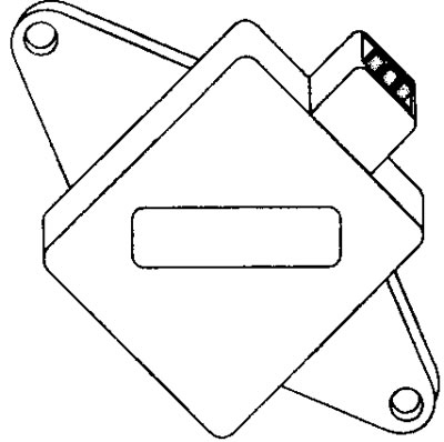
11.26 Throttle Position Sensor (TPS)
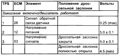
Throttle position sensor voltage values
Terminal numbers
Throttle position sensor resistance values
Note: When replacing the throttle position sensor, disconnecting the battery for approximately 15 minutes should reset the ECU memory.
Terminal numbers
| TPS | ECM | Element | Throttle position | Resistance |
| 1 and 2 | 26 and 12 | Fixed | Not installed* | |
| 1 and 3 | 26 and 53 | Signal | Closed | Not installed* |
| Open | Not installed* | |||
| 2 and 3 | 12 and 53 | Signal | Closed | Not installed* |
| Open | Not installed* |
* Although the values are not set, with the throttle valve open as described in the tests, the resistance should change evenly.
Influence of external factors
- Incorrect adjustment
- The mounting screws are too tight
- The throttle position sensor multi-pin connector is loose
- Poorly adjusted or sticking throttle valve
- Poorly adjusted or sticking throttle cable
Checking the throttle position sensor (TPS) (general check)
1. Inspect the throttle position sensor multi-pin connector for signs of corrosion or damage.
2. Make sure the connector terminal pins are properly installed and have good contact with the throttle position sensor multi-pin connector.
[You can find the original on the page: PeugeotBook.ru]
3. Any of the above faults occur as a result of a weak or unstable signal from the throttle position sensor.
Note: For different Citroen and Peugeot vehicles equipped with Bosch Motronic MP3.1, 3.2 and 5.1, several different configurations are used to connect the ECU contact pins to the throttle position sensor terminals (see the electrical connection diagram).
Checking the throttle position sensor's functionality using an oscilloscope or voltmeter
1. Bend back the rubber insulation (where possible) to the multi-contact connector of the throttle position sensor, OR connect the output unit (BB) between the multi-contact connector of the electronic control unit and the electronic control unit.
2. Connect the negative probe of the oscilloscope or voltmeter to ground at the engine OR to the ground terminal at the throttle position sensor.
3. Connect the positive probe of an oscilloscope or voltmeter to the signal wire terminal of the throttle position sensor.
4. The throttle valve is closed, the ignition is on.
5. Compare the closed throttle voltage value with the value specified in the specifications.
6. Open and close the throttle valve several times and make sure that the voltage gradually increases to a value greater than 4.25 volts.
7. If a digital voltmeter is used, it is important that it can function as a plotter.
8. If the oscilloscope time base is approximately 5 seconds, the screen may display a "waving" pattern of the throttle position sensor output signal as the throttle valve opens and then closes (see illustration 11.27).
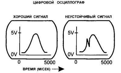
11.27 Typical Throttle Position Sensor (TPS) Output Waveform
9. If there is no throttle position sensor signal voltage, proceed to the test described below under "No Signal Voltage"
Unstable output signal
1. An unstable output signal occurs when the output voltage changes stepwise, or drops to zero, or an open circuit occurs.
2. Check for a constant resistance between the power wire terminal and the ground wire terminal, and a variable resistance between the signal wire terminal and the power wire terminal, and between the signal wire terminal and the ground wire terminal.
3. If the output signal from the throttle position sensor is unstable, the potentiometer is most likely faulty. In this case, the only solution is to replace the throttle position sensor with a new one.
The signal voltage or supply voltage matches the battery voltage
- Check for a short circuit in the wire connected to the positive (+) terminal of the battery or in the supply voltage of the sensor.
There is no signal voltage
1. Check the supply of reference voltage (5.0 V) at the power wire terminal of the throttle position sensor.
2. Check the effectiveness of the ground connection at the throttle position sensor ground wire terminal.
3. If the power and ground parts of the circuit are normal, check for continuity in the signal wire running between the throttle position sensor and the ECU.
4. If there is no power supply and/or ground, check for continuity in the power supply wire and/or ground wire running between the throttle position sensor and the ECU.
5. If the throttle position sensor wiring is OK, check all power and ground contacts of the electronic control unit. If these contacts are in working order, then the electronic control unit may be faulty.