



Table of contents: Boost control (models equipped with…🠇 Turbocharger Wastegate Voltage (WCS)…🠇 Turbocharger Wastegate Control Valve…🠇 Checking the turbocharger bypass…🠇 Checking the turbocharger wastegate…🠇 Checking the performance of the…🠇 Turbocharger bypass valve resistance 🠇
The turbocharger is located in the exhaust system quite close to the exhaust manifold.
Boost control (models equipped with a turbocharger)
When the exhaust gas volume increases, the turbocharger starts to work faster, and at high engine speeds there is a risk of over-speeding the turbocharger, which can cause engine damage. This problem is eliminated by a turbocharger wastegate (WCS).
The hose connects the turbocharger to the valve diaphragm. When the pressure rises to a certain level, the compressed air acts on the valve diaphragm, which opens to mechanically operate a flap inside the exhaust pipe. Some of the exhaust gases pass through the valve and bypass the turbocharger so that its speed is slowed down and the boost pressure is reduced.
This is the simplest way to protect the turbocharger from high pressure. However, the electronic control unit uses a control system that controls the turbocharger boost to improve power output under acceleration and at different engine speeds.
Turbocharger Wastegate (WCS) (see illustration 11.35) located in the hose connecting the turbocharger to the valve. When the turbocharger wastegate is open or partially open, the variable air volume (depending on the position of the turbocharger bypass valve) comes back out, reducing the pressure in the system.
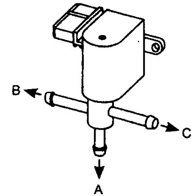
11.35 Turbocharger Wastegate Valve (WCS)
Source available on the website (PeugeotBook)
Voltage is supplied to the turbocharger wastegate from either the main relay or the fuel pump relay (depending on the model), and grounding for the valve is achieved through a connection to contact pin No. 6 of the electronic control unit.
When the engine is stopped, the turbocharger wastegate is closed and all air is directed to the turbocharger wastegate actuator. This position provides safety so that if the WCS valve fails, the boost pressure will never reach its set limit and the engine power will not be reduced. When the engine is running, the ECU pulses the wastegate valve to open so that approximately 50% of the air pumped by the turbocharger is directed directly to the valve. The electronic control unit sends pulses to the valve at a fixed frequency, and the pulse duration varies so that the valve opens for longer or shorter intervals as required. This method allows the electronic control unit to regulate the precise opening duration to achieve the correct boost pressure under all operating conditions. At engine speeds below 6,000 rpm, boost pressure is maintained at 0.9 bar. At 6,000 and 6,700 rpm, the turbocharger wastegate gradually closes, allowing more boost pressure to act on the valve. At 6700 rpm, the turbocharger wastegate closes completely and all boost pressure is directed to the valve. Boost pressure is now maintained within 0.3 bar.
If the inlet air becomes too hot (exceeds 70°C), the air density decreases and the air-fuel mixture becomes leaner. A lean mixture can lead to detonation, which in turn can cause engine damage. When the air is overheated, the electronic control unit reacts to this condition by sending pulses to close the turbocharger bypass valve to relieve the boost pressure. Lower boost pressure will reduce the air temperature and prevent detonation.
Turbocharger Wastegate Voltage (WCS) Values
Terminal numbers
| WCS | Component | Element | Volts |
| 2 | Main relay: t6 | Nutrition | nbv |
| 1 | ECM: t6 | Switch wire | nbv |
See Figure 11.5
Turbocharger Wastegate Control Valve (WCS) Resistance Values

Influence of external factors
- Manifold Absolute Pressure (MAP) Sensor
- The turbocharger wastegate is poorly adjusted or faulty
- Electronic control unit malfunction
Checking the turbocharger bypass valve (WCS)
1. Inspect the turbocharger wastegate multi-pin connector for signs of corrosion or damage.
2. Ensure that the connector terminal pins are properly installed and have good contact with the turbocharger wastegate multi-pin connector.
Checking the turbocharger wastegate control signal
1. It is very difficult to check the control signal without installing the car on a stand, since the signal is only present at engine speeds above 2500 rpm and under load.
2. The turbocharger wastegate waveform can be checked by connecting a handheld oscilloscope to the turbocharger wastegate multi-pin connector terminals.
3. However, by performing the following test procedures, the performance of the turbocharger wastegate and its circuit can be checked.
Checking the performance of the turbocharger bypass valve
1. Connect the positive probe of the voltmeter (see note 2) connect to the multi-contact connector of the turbocharger bypass valve or connect the output unit (BB) between the multi-contact connector of the electronic control unit and the electronic control unit.
2. Connect the negative probe of the oscilloscope or voltmeter to ground on the engine.
3. Connect the positive probe of an oscilloscope or voltmeter to the wire attached to the turbocharger wastegate power terminal #2.
4. Turn on the ignition, check for the presence of nominal battery voltage at the power terminal of the turbocharger bypass valve.
5. If there is no voltage, trace the wiring back to the main fuel injection relay.
6. Check the resistance of the turbocharger bypass valve.
7. Disconnect the turbocharger wastegate multi-pin connector.
8. Turn off the ignition.
9. Disconnect the electrical connectors and vacuum tubes from the valve.
10. Make sure that air does not flow from channel A to channel B, and that air does not flow from channel A to channel C.
11. Connect the jumper wire from terminal #2 to the power supply.
12. Connect the jumper wire from terminal No. 1 to ground.
13. Check that air now flows from channel A to channel B, but air does not flow from channel A to channel C.
14. If the turbocharger wastegate is activated, check the continuity of the wiring between the turbocharger wastegate and the ECU switching terminal.
15. If the turbocharger wastegate wiring is OK, check all power and ground contacts of the ECU. If these contacts are in working order, then the electronic control unit may be faulty.
Turbocharger bypass valve resistance
- Disconnect the multi-pin connector and check for voltage at the two terminals of the turbocharger wastegate