
Main relay and fuel pump relay (single double contact relay)
The Bosch Motronic electrical system is controlled by a single 15-pin double contact relay (see illustration 11.41 and 11.42). The supply of constant voltage to terminals No. 8, No. 11, No. 14 and No. 15 of the relay is carried out from the positive pole of the battery.
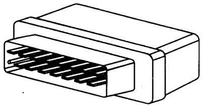
11.41 15-pin double contact relay
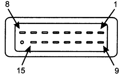
11.42 15-pin contact relay outputs
With the ignition on, the ECU connects terminal #7 of the relay to ground, which supplies power to the primary winding of the relay.
When the relay coil is energized, terminal No. 15 is connected to terminals No. 4, No. 5, No. 6 and No. 13. Thus, voltage is supplied to terminal No. 37 of the electronic control unit and to the injectors, the idle control valve and other actuators.
With the ignition on, the ECU grounds terminal #10 of the relay at pin #3 of the ECM. This energizes the secondary of the relay, which closes the second relay contact and supplies voltage from terminal #11 to terminal #9, thus providing voltage to the fuel pump circuit. After approximately one second, the electronic control unit opens the circuit and the pump stops. Running the fuel pump for a short time increases the pressure in the fuel lines and provides a quick start.
The second circuit will remain open until the engine is started or the crankshaft is cranked. Once the ECU receives a signal from the crank angle sensor, the ECM will re-energize the secondary and the fuel pump, ignition system, and fuel injection system will run until the engine stops.
Main relay
| Terminal | State | Relay | Volts |
| 8, 11, 14, 15 | Ignition off | Connected/Disconnected | nbv |
| 3 | Ignition on | Connected/Disconnected | nbv |
| 7 | Ignition on | Connected | 1.25 (max) |
| 10 | Ignition on | Connected | nbv |
| 10 | When cranking/engine running | 1.25 (max) | |
| 4, 5, 6,13 | Ignition on | nbv | |
| 1, 9 | When cranking/engine running | nbv |
| Terminal | Source/destination |
| 1 | Relay output voltage to ignition coils: t2, throttle body heater: t2, oxygen sensor: t2 |
| 2 | Not used |
| 3 | Main relay supply to relay: t5 |
| 4 | Relay output voltage to the electronic control unit: t37 |
| 5 | Relay output voltage to VASC: t2, relay: t3 |
| 6 | Relay output voltage to idle control valve: t2, carbon filter solenoid valve: t2 |
| 7 | Control relay, ECM: t36 |
| 8 | Battery power to relay: t30 |
| 9 | Relay output voltage to fuel pump 42 |
| 10 | Control relay, ECM: t3 |
| 11 | Battery power to relay: t30 |
| 12 | Not used |
| 13 | Relay output voltage to injectors: t2 |
| 14 | Battery power to relay: t30 |
| 15 | Battery power to relay: t30 |
See illustrations 11.2, 11.3, 11.4, 11.5, 11.6