
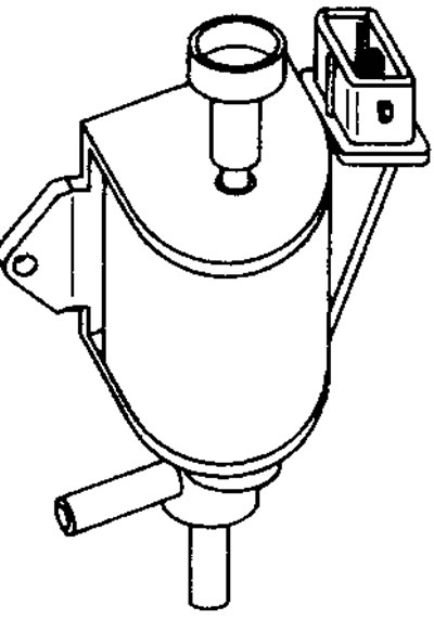
11.31 Induction changeover valve (ICOV)
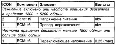
Voltage values of the induction switching valve (ICOV)
Terminal numbers
See illustrations 11.2, 11.3, 11.4, 11.5, 11.6
Resistance values of the induction switching valve (ICOV)
Terminal numbers
Checking the induction changeover valve (ICOV) (general check)
1. Inspect the multi-pin connector of the induction switching valve for signs of corrosion and damage.
2. Make sure the pins of the multi-pin connector terminals are installed properly and make good contact with the induction switching valve.
3. Check the vacuum hoses for leaks and check that they are secure.
Function test of the induction changeover valve (ICOV)
1. Connect the negative lead of an oscilloscope or voltmeter to ground on the motor.
2. Connect the positive probe of an oscilloscope or voltmeter to the wire attached to terminal #2 of the induction switching valve.
3. Turn on the ignition. The voltmeter should indicate the nominal voltage of the battery.
4. If there is no voltage, check the power supply from terminal No. 5 of the main relay.
5. Connect the positive probe of an oscilloscope or voltmeter to the wire attached to terminal #1 of the induction switching valve.
6. Turn on the ignition. The voltmeter should indicate the nominal voltage of the battery.
7. If there is no voltage, check the resistance of the induction changeover valve.
8. Start the engine and let it idle. The voltmeter should show a voltage of less than 1.0 volts.
9. If the voltage from terminal 8 exceeds the nominal voltage of the battery, skip the following checks on the induction switching valve.
10. Check the continuity of the wiring back to pin #6 of the ECU.
11. If the wiring of the induction switching valve is OK, then check the power and ground contacts of the electronic control unit. If the contacts are in working condition, then the electronic control unit may be faulty.
12. Increase the engine speed above the RPM specified in the specifications. The voltage should rise from less than 1.0V to the nominal battery voltage.
13. If this is not the case, the electronic control unit may be defective.
14. Gradually increase the engine speed above the maximum rpm specified in the specifications. The voltage should decrease by less than 1.0 volts.
15. If this is not the case, the electronic control unit may be defective.
16. Check the mechanical function of the induction changeover valve.
Checking the resistance of an induction changeover valve (ICOV)
1. Disconnect the electrical multi-pin connector from the induction changeover valve.
2. Connect an ohmmeter between the two terminals on the induction changeover valve. Compare the resulting value with the resistance specified in the specifications.
3. Connect an ohmmeter between one of these two terminals on the induction changeover valve (ICOV) and ICOV valve body. The ohmmeter should indicate infinite resistance.
Checking the mechanical function of the induction changeover valve
1. Disconnect the electrical multi-pin connector from the induction changeover valve.
2. Disconnect the two vacuum hoses to the induction changeover valve.
3. Connect the vacuum pump to the intake manifold.
4. Using the pump, create a vacuum in the intake pipe. The vacuum created must be maintained.
Note. If there is no vacuum pump, try blowing out the pipe. The attempt must fail.
5. Connect a temporary jumper wire from one terminal of the induction switching valve to the positive battery terminal.
6. Connect a temporary jumper wire from the other terminal of the induction switching valve to the negative battery terminal.
7. Using the pump, create a vacuum in the intake pipe. The created vacuum should not be maintained, and it is now possible to blow the intake pipe to the exhaust.
Checking the function of the ICOV control valve
1. Disconnect the vacuum hose from the ICOV control valve.
2. Connect a vacuum pump to the inlet pipe of the ICOV control valve.
3. Create a vacuum of 300 mmHg. for ICOV control valve. The control valve must move quickly and smoothly to fully open the ICOV damper.
4. Remove vacuum. The control valve must move quickly and smoothly to fully open the ICOV damper.
5. Connect the vacuum hose to the ICOV control valve.