
English Русский
Български
Беларускі
Український
Српски
Hrvatski
Română
Polski
Slovenský
Magyar
Bookmark Articles Sitemap Contacts
Company Hyundai Company Opel Company Skoda Company Kia Company Mitsubishi Company LADA Company Audi
PeugeotBook.ru


Series 100   Series 200   Series 300   400-500   Series 600   Crossovers   Others
 
Partner I (1996-2008) Peugeot 807 (2002-2014) Peugeot 806 (1994-2002) Peugeot J5 (1981-1993)

Vehicle Speed Sensor (VSS) (Peugeot Eurovans 806)

  • Main
  • Пежо
  • Peugeot 806 (1994-2002)
  • Power unit
  • ECM Bosch Motronic MP 3.2
  • Vehicle Speed Sensor (VSS)
0
Table of contents: Vehicle Speed Sensor (VSS) Voltage…🠇 Vehicle Speed Sensor (VSS) Frequency 🠇 Checking the vehicle speed sensor…🠇 Checking the functionality of the…🠇 Checking the signal from the vehicle…🠇 No signal or signal is unstable,…🠇 The voltage in the grounding and…🠇 There is no signal voltage 🠇
Vehicle Speed Sensor (VSS) (see illustration 11.28) used to notify the electronic control unit of the vehicle's speed. This sensor is a Hall sensor and is located directly on the gearbox. Voltage is supplied to the vehicle speed sensor from the energized relay. When the speedometer drive cable rotates, the Hall sensor alternately turns on and off to send a square wave signal to the electronic control unit. Signal frequency (8 pulses per revolution) determines the speed of the car.
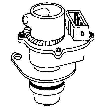
11.28 Vehicle Speed Sensor (VSS)

11.28 Vehicle Speed Sensor (VSS)


Vehicle Speed Sensor (VSS) Voltage Values


Terminal numbers
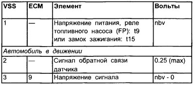


Terminal numbers
See illustration 11.29


11.29 Vehicle speed sensor wiring diagram

11.29 Vehicle speed sensor wiring diagram


Vehicle Speed Sensor (VSS) Frequency


8 pulses per revolution of the speedometer drive cable.

Checking the vehicle speed sensor (VSS) (general check)


1. Inspect the vehicle speed sensor multi-pin connector for signs of corrosion or damage.

2. Make sure the connector terminal pins are properly installed and have good contact with the vehicle speed sensor connector.

Checking the functionality of the vehicle speed sensor (VSS)


1. The test is quite simple. The sensor has three wires: a power wire, a ground wire, and a signal wire.

2. Connect the positive lead of the voltmeter to the vehicle speed sensor multi-pin connector (see note 2) or connect the output block (OB) between the ECU multi-pin connector and the ECU.

3. Connect the negative probe of an oscilloscope, breaker duration meter, or voltmeter to ground on the engine.

4. Connect the positive probe of an oscilloscope, contact duration meter, or voltmeter to terminal #3 of the vehicle speed sensor signal wire (see illustration 11.30).
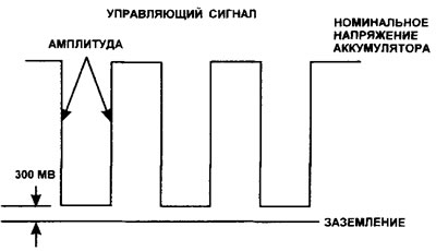
11.30 Typical waveform of the vehicle speed sensor (VSS) output signal

11.30 Typical waveform of the vehicle speed sensor (VSS) output signal


Checking the signal from the vehicle speed sensor (VSS)


Note: The supply voltage can be generated from the ignition switch or a relay. If the voltage is supplied from a relay, the connection can be from the first or second contact of the relay. The first relay contact supplies voltage when the ignition is on, the second relay contact supplies voltage only when the engine is running.


1. Turn on the ignition or start the engine.

2. The signal is sent by the sensor when the drive wheels rotate. Wheel rotation can be achieved in one of two ways:
  • Push the car forward.
  • Place the vehicle on an inclined plane so that the drive wheels can rotate freely. Either spin the wheels manually or start the engine at low speed.

3. The device should display the waveform, duty cycle or voltage.

No signal or signal is unstable, duty cycle or voltage


1. The vehicle speed sensor multi-pin connector is disconnected, ignition is on.

2. Check the voltage supply to the vehicle speed sensor power wire terminal.

3. No voltage: Check the voltage supply from the ignition switch or relay, depending on the system design.

4. Check the ground at the vehicle speed sensor ground wire terminal.

5. Disconnect the vehicle speed sensor multi-pin connector.

6. Connect the positive probe of the voltmeter to the signal wire terminal.

7. The device should indicate voltage between 8.5 and 10.0 Volts.

The voltage in the grounding and power supply wires is within normal limits


  • The vehicle speed sensor may be faulty or not turning the speedometer drive (i.e. the cable is broken or there is a malfunction in the gearbox).


There is no signal voltage


1. Check the voltage at the multi-pin connector terminal of the electronic control unit.

2. If the voltage of the electronic control unit is within the normal range, check the signal wire for continuity.

3. If there is no voltage at the contact of the electronic control unit, then check the power and ground contacts of the unit. If the contacts are in working order, then the electronic control unit may be faulty.

(Original can be viewed at: «PeugeotBook.ru»)
This article is available at russian, bulgarian, belarusian, ukrainian, serbian, croatian, romanian, polish, slovak, hungarian
Article reviewed by editor: Shirokov Arseny
Share information:
Previous
Peugeot 806: ECM Bosch Motronic MP 3.2
Next

Throttle position sensor (TPS)
Manifold Absolute Pressure (MAP) Sensor
Knock sensor (KS)
Intake air temperature sensor and coolant temperature sensor…
Ignition coils of the direct ignition system
Induction Changeover Valve (ICOV) (non-turbocharged models only)
Idle Air Control Valve (ISCV)
Intake Manifold Heater (IMH)
Turbocharger Wastegate (WCS) (with turbocharger only)
Fuel injection system
See similar information for other Peugeot models

➨ Idle speed and mixture check and adjustment Peugeot 106 (1991-2003)
➨ Removal and installation the vehicle speed sensor Peugeot 206 (1998-2012)
➨ Basic operations that can be carried out without removing the… Peugeot 305 (1977-1989)
➨ Vehicle identification Peugeot 405 (1987-1997)
➨ Vehicle care Peugeot 605 (1989-2000)
Link to this article in different formats
Comments and feedback from visitors
No comments yet


Add two numbers 19 + 17


Partner I (1996-2008) 
  • General information
  • Introduction to the guide
  • Faults en route
  • Weekly checks
  • User manual
  • Maintenance (petrol)
  • Maintenance (diesel)
  • Power unit
  • Petrol engines
  • Diesel engines «XUD»
  • Diesel engines «DW»
  • Overhaul of petrol engines
  • Overhaul of diesel engines
  • Cooling and heating
  • Power and exhaust (petrol)
  • Power and exhaust (XUD diesels)
  • Power and exhaust (DW diesels)
  • Emission reduction
  • Starting and charging system
  • Transmission
  • Clutch
  • Mechanical gearbox
  • Drive shafts
  • Chassis, running gear
  • Brake system
  • Car suspension
  • Steering
  • Body and interior
  • Exterior (external elements)
  • Interior (internal elements)
  • Doors, locks and windows
  • Electrical equipment
  • Equipment and devices
  • Electrical circuits
Peugeot 807 (2002-2014) 
  • General information
  • Operating instructions
  • Maintenance
  • Troubleshooting
  • Power unit
  • Gasoline engines
  • Diesel engines
  • Cooling and heating
  • Fuel injection (petrol)
  • Fuel system (diesel)
  • Fuel system
  • Exhaust system
  • Ignition system
  • Transmission
  • Clutch
  • Manual gearbox
  • Automatic gearbox
  • Chassis, running gear
  • Brake system
  • Car suspension
  • Steering system
  • Body and interior
  • Exterior (external elements)
  • Interior (internal elements)
  • Electrical equipment
  • Power devices
  • Electrical circuits
Peugeot 806 (1994-2002) 
  • General information
  • User manual
  • Maintenance
  • Power unit
  • Petrol engines
  • Diesel engines
  • Lubrication system
  • Cooling system
  • Fuel injection (petrol)
  • Fuel system (diesel)
  • Ignition and exhaust systems
  • ECM Bosch Motronic MP 3.2
  • ECM Magneti-Marelli (MM)
  • Transmission
  • Clutch
  • Mechanical gearbox
  • Chassis, running gear
  • Brake system
  • Car suspension
  • Steering
  • Electrical equipment
  • Equipment and devices
  • Electrical circuits
Peugeot J5 (1981-1993) 
  • General information
  • Introduction to manual
  • Specifications
  • Gasoline engine
  • Engine repair
  • Lubrication system
  • Cooling system
  • Fuel system
  • Ignition system
  • Diesel engine
  • Engine repair (DB9)
  • Lubrication system (DB9)
  • Cooling system (DB9)
  • Fuel injection (DB9)
  • Engine repair (U25)
  • Lubrication system (U25)
  • Cooling system (U25)
  • Fuel injection (U25)
  • Transmission
  • Clutch
  • Gearbox
  • Drive shafts
  • Chassis, running gear
  • Steering system
  • Car suspension
  • Brake system
  • Electrical equipment
  • Power devices
  • Electrical circuits
PeugeotBook.ru © 2018–2026 | Mobile version | Sitemap: EN BG BY UA RS HR RO PL SK HU | Write message | Site search | Add to bookmarks | Peugeot owners
106 (1991-2003) | 206 (1998-2012) | 207 (2006-2014) | 305 (1977-1989) | 306 (1993-2002) | 307 (2001-2008) | 405 (1987-1997) | 406 (1995-2004) | 605 (1989-2000) | Partner-I (1996-2008) | Eurovans-807 (2002-2014) | Eurovans-806 (1994-2002) | J5 (1981-1993) |
Cookies are used to ensure the correct display of pages on the site.