



Table of contents: Oxygen (O2) sensor voltage values 🠇 Influence of external factors 🠇 Checking the signal from the oxygen…🠇 Oxygen sensor switching 🠇 Oxygen sensor heater tests 🠇
Oxygen (O2) Sensor Closed Loop Voltage (see illustration 11.44) the signal frequency is quite low, ranging from 100 mV to 1.0 V. The signal frequency is approximately 1 Hz. A digital voltmeter connected to the signal wire will show an average voltage of approximately 0.45 volts. In the event of a fault in the oxygen sensor circuit, the electronic control unit supplies a constant voltage of 0.45 volts, and this should not be confused with the average voltage of 0.45 volts, which is created when switching from approximately 1.0 volts to 0.1 volts.
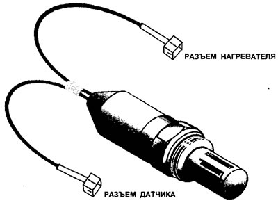
11.44 Oxygen sensor (O2)
The signal from the oxygen sensor, operating in a closed loop, causes the electronic control unit to change the injector timing in such a way that the composition of the air-fuel mixture is maintained as close as possible to the stoichiometric ratio. By controlling the fuel injection stroke, under most operating conditions, so that the air-fuel mixture composition is always in a small window around the Lambda point (i.e. Lambda = 0.981.04), at which almost complete combustion is achieved.
The oxygen sensor operates in closed loop when the engine is at normal operating temperature. If the coolant temperature is below 70°C or the engine load is at or above the limit, the electronic control unit will operate in open loop. When operating in open loop, the ECU regulates the air-fuel mixture, making it richer or leaner than required for the stoichiometric ratio. This prevents the engine from running rough, for example when accelerating with the throttle wide open.
To ensure that the oxygen sensor reaches its maximum operating temperature as quickly as possible after the engine is started, it contains a heating element.
The supply voltage to the oxygen sensor heater comes from terminal No. 9 of the main relay (fuel pump) (for 306 models only) or to terminal No. 1 (ignition coil and intake manifold heater) (for all other models). Terminals #1 and #9 are grouped together in the relay. Therefore, the oxygen sensor heater will only function when the engine is running.
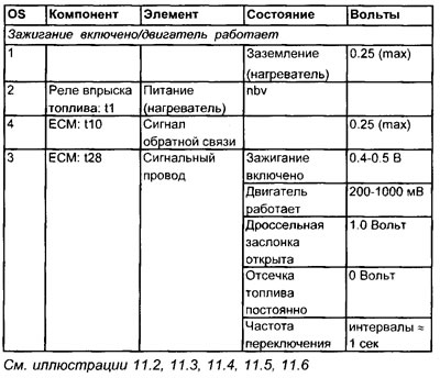
Oxygen (O2) sensor voltage values
Terminal numbers
Influence of external factors
- Poor grounding of the oxygen sensor
- The oxygen sensor is dirty
- Vacuum leaks
- Malfunction of the ignition system or fuel system
- Oil liquefaction
- The air filter is clogged
- Leaded gasoline
- Low fuel pressure
- Exhaust leaks (main oxygen sensor)
Checking the signal from the oxygen sensor
1. Connect the negative probe of the oscilloscope or voltmeter to ground on the engine.
2. Connect the positive probe of an oscilloscope or voltmeter to terminal #3 of the oxygen sensor signal wire.
3. If possible, connect a gas analyzer to the exhaust system that determines the content of 4 gases and the lambda parameter.
4. The gas analyzer should show the following values:
- CO: as specified in the specifications
- NS: less than 50 ppm
- CO₂: more than 15.0
- O₂: less than 2.0
- Lambda: 1.0±0.04
Oxygen sensor switching
1. Ignition on: the device should show 0.5 Volts.
2. If there is no voltage, check the continuity of the wiring back to the ECU signal wire terminal.
3. Start the engine and warm it up to normal operating temperature.
4. Increase the engine speed to 3000 rpm for 30 seconds. This will raise the oxygen sensor temperature enough for the switch to occur.
5. Maintain engine speed at 2000 rpm. If the engine is left idling for a long time, the oxygen sensor will cool down and switching may stop.
6. The voltage will change from approximately 0.8 volts (800 mV) to 0.2 volts (200 mV).
7. The digital voltmeter will indicate an average voltage of approximately 0.45 volts (450 mV).
8. Switching frequency - approximately 1 Hz (that is, one pulse per second).
9. If the oscilloscope can set the time base to be greater than one second, a sinusoidal switching waveform can be obtained (see illustration 11.45).
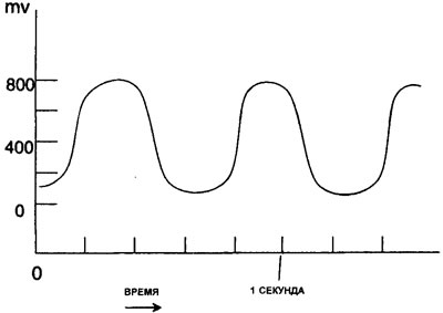
11.45 Typical output signal from the oxygen sensor (O2)
10. If the voltage reading is generally between 0.6V and 1.0V, then the gases in the exhaust pipe have a small amount of oxygen, indicating a rich mixture (see illustration 11.46).
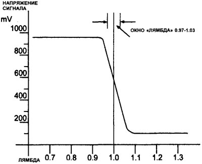
11.46 Typical diagram of output voltage relative to "lambda"
11. If the voltage is generally between 0.2V and 0.6V, the gases in the exhaust pipe have too much oxygen. This may indicate one of the following conditions:
- Vacuum leak
- Lean mixture
- Misfire
- Mechanical failure
- Ignition system malfunction
- Exhaust gas leak before the oxygen (O2) sensor
- Slow switching (much more than 1 Hertz) may indicate contamination of the oxygen sensor.
Oxygen sensor heater tests
1. Check for battery voltage at terminal #2 of the oxygen sensor.
2. If there is no voltage, trace the power wiring back to the relay or ignition switch (depending on the system device).
3. Check the ground contact of the oxygen sensor heater.
Original is located at (peugeotbook)