



Table of contents: Removal 🠇 Refitting 🠇
Note: Refer to the warning note in Section 1 before proceeding.
Removal
1. Disconnect the battery negative terminal (refer to "Disconnecting the battery").
2. Remove the air cleaner housing-to-throttle body duct, using the information given in Section 2.
3. Depress the retaining clips and disconnect the wiring connectors from the throttle potentiometer, the idle control stepper motor and the injector wiring loom connector, which is situated on the side of the throttle body (see illustration). On later 1124 cc models (with the Magneti Marelli system) the injector, heating element and inlet air temperature sensor wiring are all joined to one large connector.
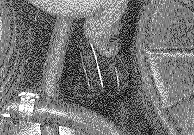
12.3a. Disconnect the wiring connectors from the throttle potentiometer...
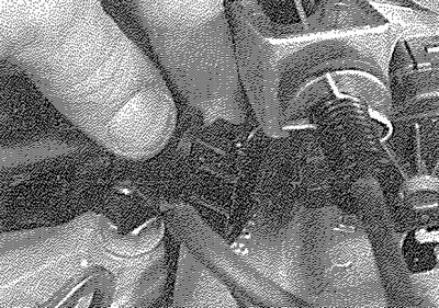
12.3b.... the injector cap and the stepper motor
4. Bearing in mind the information given in Section 8 about depressurising the fuel system, release the retaining clips and disconnect the fuel feed and return hoses from the throttle body assembly (see illustration). If the original crimped-type clips are still fitted, cut the clips and discard them; replace them with standard worm-drive hose clips on refitting.
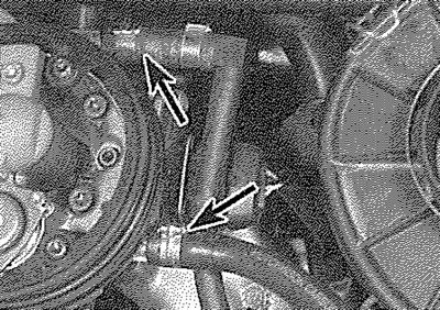
12.4. Fuel feed and return hose connections (arrowed) - later model shown
5. Disconnect the accelerator inner cable from the throttle cam, then withdraw the outer cable from the mounting bracket, along with its flat washer and spring clip.
6. Where necessary, disconnect the distributor vacuum hose, idle control auxiliary air valve and/or purge valve hose from the throttle body (as applicable).
7. Slacken and remove the bolts securing the throttle body assembly to the inlet manifold (see illustration), then remove the assembly along with its gasket.
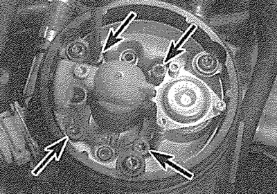
12.7. Throttle body retaining screws (arrowed)
8. If necessary, with the throttle body removed, undo the retaining screws and separate the upper and lower sections, noting the insulating spacer and gaskets, or the single gasket (as applicable) fitted between the two.
Refitting
9. Refitting is a reverse of the removal procedure, bearing in mind the following points:
- a) Where applicable, ensure that the mating surfaces of the upper and lower throttle body sections are clean and dry, then fit the insulating spacer and new gaskets, or a new gasket (as applicable) and reassemble the two, tightening the retaining screws securely.
- b) Ensure that the mating surfaces of the manifold and throttle body are clean and dry, then fit a new gasket. Securely tighten the throttle body retaining bolts.
- c) Ensure that all hoses are correctly reconnected and, where necessary, that their retaining clips are securely tightened.
- d) On completion, adjust the accelerator cable using the information given in Section 4.