



Table of contents: 15.1.1. Removal 🠇 15.1.2. Installing the power unit 🠇
15.1.1. Removal
As mentioned in the introduction, there are differences between the three vehicles described. The instructions below apply to all models.
The engine is pulled out of the engine compartment together with the gearbox, meaning the removed unit is quite heavy. In workshops, a lifting beam is used for this purpose, the chains of which are hooked onto the lifting eyes on the top side of the head.
The lifting eyes are also a special tool and are bolted to the engine. Therefore, some preliminary work is required to suspend the engine using cables or chains. It is important that the crane or pulley used has a load capacity greater than the weight of the engine. The lifting eyes should be screwed in from the water pump side and the clutch side. If the lifting beam is made independently, it must also be strong enough so that it does not sag. You can make your own lifting beam, just like the one shown in the picture figure 8.
When removing the engine, the following general guidelines must be observed:
- When removing the power unit, the car's wheels should sag under their own weight, that is, the wishbones should not be raised.
- It is not necessary to drain the oil from the engine and gearbox.
- Do not separate the steering rod ball joints and the front wheel suspension ball joints. To disconnect, it is best to unscrew the bolts securing the ball joints from the steering knuckles.
- The left and right drive shafts are removed differently. A drift is required to remove the axle shaft (see description below).
- The right axle shaft is held in the middle by a support bolted to the cylinder block.
- The cooling system is filled with antifreeze throughout the year. After installing the engine, fill the cooling system with coolant.
- When removing, the wheel hub caps may be damaged. Therefore, they should be removed with extreme care.
The engine is removed as follows:
- Remove the spare tire.
- Disconnect the ground wire from the battery. The battery can also be removed as an option.
- Drain the coolant from the cooling system. The drain cock is inserted into the radiator, in addition, the plug from the cylinder block should be unscrewed.
- Disconnect the wires and connectors of the following consumers: headlights and turn signals, temperature switch on the water pump, temperature switch on the radiator, temperature switch on the cooling jacket and wires connected to the air filter.
- Unscrew the engine compartment hood locking mechanism from the radiator grille.
- Release the rear spare wheel mount.
- Unscrew the two bolts (1) and nuts (2) in Figure 211 and remove the entire radiator grille (front).
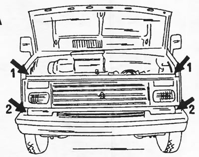
Figure 211. The front trim of the car is secured with two bolts (1) and two nuts (2).
- Remove the air filter.
- After loosening the clamp, disconnect the hose from the vacuum pump. In close proximity is the rubber disc of the hinge. Loosen the bolts and nuts and disconnect the hinge. The mentioned details are shown in Figure 212.
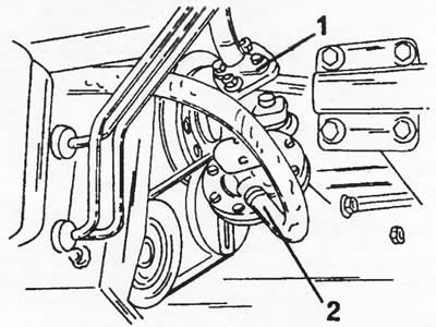
Figure 212. To remove the engine, disconnect the rubber disc of the joint (1) and the vacuum pump hose (2), which ensures the operation of the brake booster.
- When disconnecting and removing the following parts, use Figure 213. Disconnect: heater hoses (3) from the radiator tank, heater and cylinder block, hoses (5) from the fuel filter and hose (6) from the fuel return line to the tank. The cooling system expansion tank (1), air intake housing (2) and fuel filter (4) must be removed.
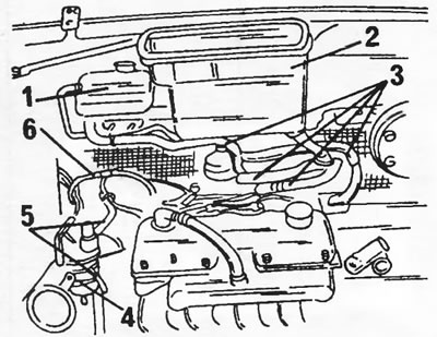
Figure 213. Removing the diesel engine. 1. Expansion tank of the cooling system; 2. Air intake housing; 3. Connecting the heater hoses; 4. Fuel filter; 5. Hose; 6. Return fuel hose
As mentioned, the location of the parts may vary depending on the type of engine installed.
- Disconnect the following wires and connectors: alternator dual connector, idle air control solenoid wire, glow plug wires, starter wires, oil temperature switch wire, reverse light switch wires, and ground jumper wire from the engine block.
- Disconnect the throttle cable from the high pressure fuel pump lever.
- Trace the flexible shaft gasket of the speedometer and unscrew the union nut on the gearbox.
- Disconnect the clutch cable from the clutch release lever. To do this, loosen both adjusting nuts on the clutch cable support so that the cable can be pulled out of the clutch release fork.
Next, the drive shafts are disconnected from the right and left sides of the gearbox, taking into account the following differences:
On the right side
- Remove the wheel hub cap. To do this, tap around the circle with a flat chisel, inserting it between the cap and the wheel hub. If the hubcap does not give in, you will need to remove the wheel after raising the car. This will make the job easier. At the service station, the wheel hub cap is removed using a puller.
- Unlock and unscrew the hub nut. In this case, the wheel must be on the ground, that is, if the hub cap was removed while the wheel was removed, then to loosen the nut, you need to put the wheel back on. Never loosen the nut when the vehicle is on stands.
- Unscrew the bolts (3) shown in Figure 214 from the bottom of the wheel suspension. The bolts secure the ball joint to the steering knuckle. Also unscrew the steering knuckle arm bolts (1) from the steering knuckle.
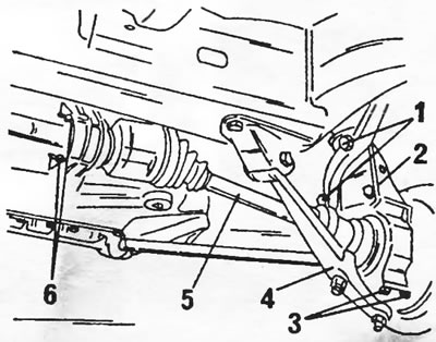
Figure 214. Removing and installing the right drive shaft. References to figures are given in the text.
- After this, press the ball joint out of the steering knuckle. If it fits tightly, it's best to put the wheel back on. After this, holding the wheel, grab the transverse lever and pull it down, as shown in Figure 215.
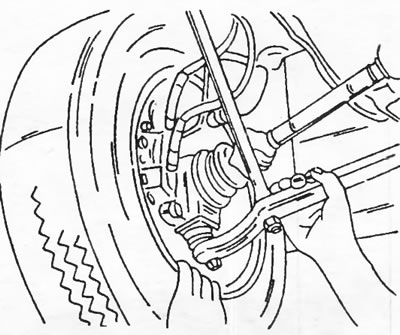
Figure 215. Press the wheel outward, grab the transverse lever in the manner shown and pull it sharply downwards. The vehicle must be securely supported on stands. Check the vehicle installation beforehand.
- Tilt the steering knuckle (2) assembly outward while simultaneously removing the end of the drive shaft (6) from the wheel hub.
- Loosen both nuts (6) of the drive shaft support bearing and move both tension bars.
- Unscrew the bolts (3) shown in Figure 214 from the bottom of the wheel suspension. The bolts secure the ball joint to the steering knuckle. Also unscrew the bolts (2) of the steering knuckle arm from the steering knuckle.
- Insert a chisel between the CV joint housing and the drive bolt as shown in Figure 216 and tap gently with a hammer without damaging any parts.
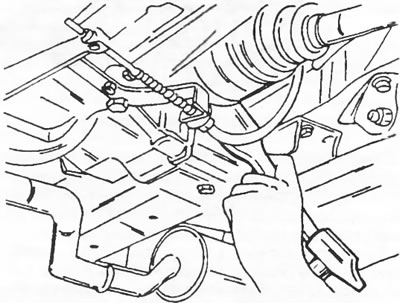
Figure 216. Insert a chisel at the indicated location between the constant velocity joint housing and the drive bolt.
- Check the chisel installation again and carefully tap the end of the chisel with a hammer as shown in Figure 217. This will cause the retaining ring on the end of the drive shaft to pop out of the groove in the differential gear side gear and the shaft to be released. Pull the drive shaft out of the transmission by pulling the steering knuckle outward. Protect the end of the wada from contamination.
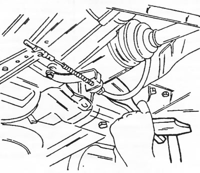
Figure 217. Check the installation of the chisel and carefully hit the end of the chisel with a hammer
Loosen the exhaust pipe connection nuts and disconnect the pipes.
After this, the mentioned lifting eyes must be screwed onto the engine. First, remove the engine mount bolts on the right side above the alternator. These bolts are located on the right and left sides and are located on the right side of the engine, similar to how it is shown in Figure 17 for a gasoline engine.
- Connect the lifting bracket shown in Figure 8 or a similar device to the lifting lugs using chains. Connect this entire system to a crane or pulley block and lift until the power unit begins to shift.
- Loosen the four upper bolts of the powertrain center mount. Once again, check that all connections are disconnected and lift the power unit, removing it from the engine compartment. Always ensure that connections, wires, pipes, etc. are not caught and that all connections are disconnected.
After removal, place the power unit on a stand, for example made of wood, and secure it to prevent it from tipping over. After this, inspect the entire power unit for external damage, including any signs of oil leakage, which may indicate the presence of damaged parts. After this, clean the engine from the outside. Cover all sensitive areas.
Source available here: PEUGEOTBOOK.ru
15.1.2. Installing the power unit
The power unit is installed in reverse order. In this case, it is necessary to follow the following instructions:
- Be sure to replace all self-locking nuts, lock washers and other wearing parts.
- Prepare the engine compartment so that the power unit can be easily inserted into it.
- All loose parts, wires, hoses, etc., must be tied or glued with adhesive tape to the outer walls of the compartment.
- Thoroughly clean the connection areas and check for rust, etc.
- Raise the engine and gearbox to the desired position, install the engine mount, and tighten the bolts on the left and right sides to a torque of 55 Nm. Tighten the lower gearbox mount bolts to the same torque.
- When installing the left axle shaft, ensure that the new snap ring on the end of the axle shaft is retained in the inside of the side gear in the differential. You can check this by twitching the axle shaft. Don't forget to install the O-ring on the drive shaft.
- Place the transverse arm onto the steering knuckle as shown in Figure 215 and screw in the bolts. Tighten the bolts evenly in a circle to a torque of 50 Nm.
- Secure the steering knuckle arm with two bolts. Tighten the bolts to a torque of 125 Nm.
When installing the right drive shaft:
- Turn the steering wheel all the way to the left and insert the drive shaft into the support bearing (2) in Figure 218. Install the dust protection ring (5), Teflon ring (6) and O-ring (7) in sequence.
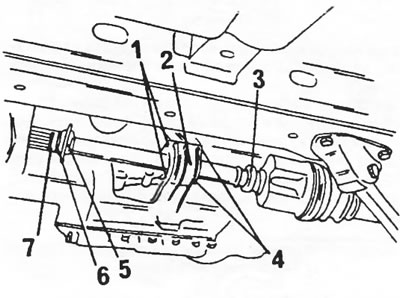
Figure 218. To install the right drive shaft. 1. Nuts, 7 nm; 2. Fastening the support bearing; 3. Bearing; 4. Clamping bar; 5. Dust ring; 6. Teflon ring; 7. Round section seal
- Slide the bearing (3) into the ring (5) and turn the clamping bar half a turn to clamp the outer ring of the bearing.
- Fill the working surface under the dust ring with grease and insert the drive shaft into the wheel hub.
- Place the ball joint plate against the steering knuckle and tighten the bolts evenly in a circle to a tightening torque of 50 Nm.
- Install the steering knuckle arm. Tighten both bolts to 125 Nm.
- The connection between the exhaust pipe and the manifold must be tightened in a certain way. Sealing cones must be lubricated with heat-resistant grease. This is, for example, lubricant "Gripcott-Fett A-F". Other types of lubricant can be found at the service station. Place the springs and washers and tighten the nuts until the springs are compressed. After this, loosen each nut by half a turn.
- Insert the clutch cable into the support on the gearbox and pass the rod with the cable through the release fork roller. Check the cable connection to the clutch pedal.
- Connect the speedometer shaft.
- Connect the throttle cable.
- After this, it is necessary to adjust the clutch pedal. In this case, it is not the free play that is adjusted. and the height of the clutch pedal. The assistant should observe the pedal. After connecting the cable, tighten both nuts on the release fork ("1" and "2" in Figure 219) so that the clutch pedal is at the same height as the brake pedal. After this, lock the nut.
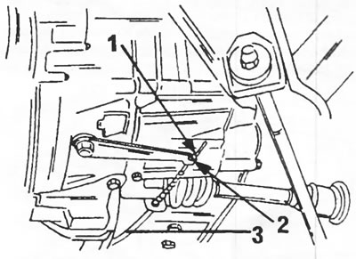
Figure 219. Adjusting the clutch on a vehicle with a diesel engine. 1. Adjusting nut; 2. Lock nut; 3. Clutch cable
- Reconnect all disconnected wires. The same applies to hoses.
- Lower the car. Lubricate the right drive shaft threads with Loctite and tighten the nut to 50 Nm. Hammer the nut boss on both opposite sides to secure the nut. Install the wheel hub cap.
- Fill the cooling system with coolant. Be sure to fill with antifreeze of the type intended for the given engine.
- Remove air from the fuel filter.