



Table of contents: 2.1.1 Removing TU engines 🠇 2.1.2 Installation of the power unit…🠇 2.1.3 Removing the power unit - XU…🠇 2.1.4 Installing the power unit - XU…🠇
2.1.1 Removing TU engines
The engine together with the gearbox is pulled upward. This job requires a strong lifting device, but the engine can be removed with two strong helpers. To remove the engine, the front of the car must be placed on stands. In the following text, the description of removal is given in general terms, since it is impossible to give a description for each individual engine in all details. Depending on the model, some work must be adjusted:
- Remove the decorative wheel covers (removing one bolt on each wheel). Tighten the handbrake and loosen the drive shaft nuts with the appropriate wrench head, without unscrewing the nuts, as shown in Figure 7.
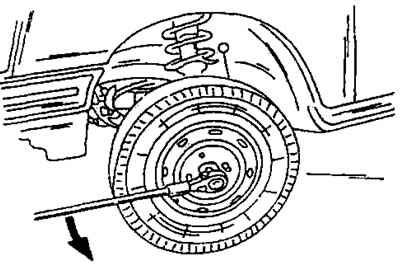
Figure 7. Loosening the drive shaft nuts. The wheel must stand on the ground.
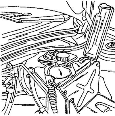
Figure 8. Open the cover and disconnect the wiring harness.
- Disconnect the wires from the battery and remove the battery.
- Remove the air filter.
- Open the cover shown in Figure 8 and disconnect the engine wiring harness from the ECM.
- Drain the coolant from the cooling system. Drainage is carried out in accordance with the instructions in the section "Cooling system". If the coolant is not yet old, drain it into a clean container. The coolant contains antifreeze and can be reused if it has not been in the cooling system for a long time. Otherwise, the disposal of the coolant is carried out in compliance with environmental protection regulations.
- Drain the oil from the gearbox and axle reducer. This requires a square socket wrench. The oil is drained from the engine if work on the engine is planned that requires draining the engine oil from the engine.
- Disconnect all electrical wires connected to the power unit. In the place shown in Figure 9, two wires are screwed on, which should also be disconnected.
(Text taken from the website: «peugeotbook.ru»)
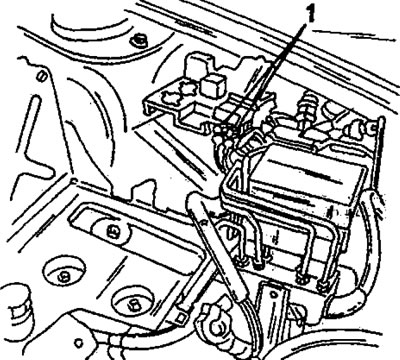
Figure 9. Unscrew the fastening of two wires (1).
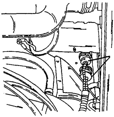
Figure 10. Disconnect both connectors
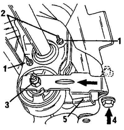
Figure 11. Removing the reaction support. 1. Locknuts; 2. Bolts; 3. Nut and bolt; 4. Mounting bolt
- Unscrew the battery bracket.
- Raise the front of the car and place strong stands under the body.
- Disconnect the two connectors shown in Figure 10.
- Disconnect the hoses from the heater fittings. The hoses have special fastening locks. There are small levers on both hoses. They should be turned to the right and the hoses pulled out.
- To remove the power unit, it is necessary to set the engine compartment hood in a vertical position. Since a special tool is required to hold the hood in this position, it is best to unscrew the hood and set it aside in a safe place. To do this, mark the contours of the hinges on the hood with a pencil and unscrew the hinge bolts. While unscrewing the last bolt, have an assistant hold the hood.
- Unscrew the exhaust pipe from the manifold (3 nuts) and release it from the mount on the gearbox. Lower the pipe down.
The following work is carried out using Figure 11:
5. Reactive support
- Loosen the bolt (3).
- Loosen the bolt (4) and pull out the reaction support.
- Loosen both lock nuts (1) and unscrew the bolts (2) approximately a quarter of a turn from engagement with the retainer.
- Place the front of the car on stands and remove the wheels.
- Press the right and left ball joints out of the steering knuckles as described in the section "Front wheel suspension". The connection between the steering knuckle and the ball joint journal is secured with a tie bolt.
- Remove both drive shafts in accordance with the instructions in the relevant section.
- Disconnect the speedometer flexible shaft.
- Disconnect the gear shift rods from the gearbox. They are shown in Figure 12.
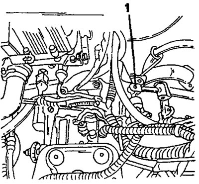
Figure 12. Connection point of gear shift rods.
Remove the following parts in sequence:
- Disconnect the fuel supply hose.
- Disconnect the throttle cable.
- Disconnect all components belonging to the fuel injection system.
- Disconnect the water pump outlet hose.
- Disconnect the electrical wires from the gearbox (for example, the starter wire and the reverse light switch wire).
- Disconnect the vacuum hose from the brake booster.
- Attach the power unit to a crane or other suitable lifting device using chains or cables and slowly pull the power unit until the chains or cables are taut. To avoid damaging the radiator during subsequent work, cut a sheet of thick cardboard the size of the radiator block and insert it in front of the radiator block.
- Unscrew the nuts securing the engine block supports on the left and right. Both engine mounts are shown in Figures 13 and 14, that is, one mount is located on the right side on the timing case, and the second mount is on the left side, on the clutch side under the battery bracket.
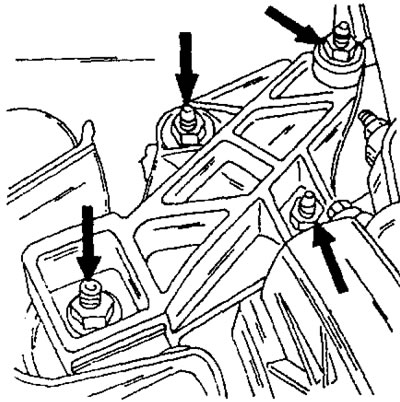
Figure 13. The arrows indicate the nuts securing the right engine mount. All bolts are tightened to a torque of 45 Nm.
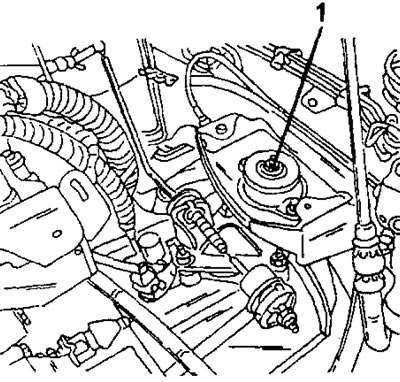
Figure 14. The left engine mount is secured to the support with nut (1). The nut has a tightening torque of 65 Nm.
- Once again, make sure that all connections are made, lift the power unit and remove it from the engine compartment. At the same time, constantly ensure that tubes, hoses, wires, etc. do not get caught on the power unit and that all disconnections are made.
After removal, place the engine on a suitable support, such as a wooden block, and secure the power unit from tipping over. After this, inspect the entire power unit for external damage and leaks, such as traces of oil, which may indicate damaged parts. After this, clean the outside of the engine. Cover all sensitive parts.
2.1.2 Installation of the power unit - TU engine
The power unit is installed in reverse order. In this case, it is necessary to follow the following instructions:
- Be sure to replace all self-locking nuts, lock washers, drive seals and other wear parts.
- Prepare the engine compartment so that the power unit can be inserted.
- All released parts, wires, hoses, etc. should be secured to the outer walls or sealed with adhesive tape.
- Thoroughly clean the connection areas and check for corrosion, etc.
- Before installing the engine, do not forget, as already mentioned, to replace the seals of the drive shafts located in the gearbox. The relevant work is described in the section on removing and installing drive shafts. Before installation, lightly lubricate both seals with engine oil and place grease between the sealing lips.
- After installing the power unit, fill the engine with coolant and engine oil. Filling capacities are indicated in the tables of sizes and adjustments at the end of the book.
- Lower the power unit to the desired position until the engine mount is level and install the engine support on the left side (looking at the car from the front). The support is shown in Figure 13. Tighten all engine mount bolts to 45 Nm.
- Raise the power unit enough to place the engine mount shown in Figure 14 on the stud. Screw on the nut and tighten it to a tightening torque of 65 Nm.
- To adjust the clutch, you need to disconnect the return spring from the clutch release fork and loosen the clutch cable lock nut. After this, adjust the clutch cable so that there is no play on the clutch lever. After this, adjust the nut on the end of the clutch cable so that the distance from the pedal lever to the floor is 141 mm. Then reconnect the spring. The adjustment is also described in the "Clutch" section.
- After this, install both drive shafts in accordance with the instructions in the relevant section.
- Restore the connection of the ball joints with the steering knuckles. To do this, the transverse arm is pressed upward so that the support tip enters the steering knuckle. Tighten the tie bolt and nut to a torque of 45 Nm. Work on both sides.
- Install the rear suspension of the power unit using Figure 11. After placing the suspension in the position shown in the figure, tighten the bolt and nut (4) to a torque of 70 Nm, the bolt (3) to a torque of 50 Nm and the nuts (1) to a torque of 10 Nm.
- Install a new exhaust manifold flange gasket and connect the pipe flange to the manifold. Secure the muffler pipe to the gearbox bracket.
- Connect the outlet hose to the water pump, secure the heater hoses to the bulkhead and make the appropriate connections to the fuel injection system.
- Connect the speedometer flexible shaft.
- Connect the engine wiring harness.
- Connect the gear shift rods to the gearbox.
- All other work is carried out in reverse order. The tightness of the cooling system is checked using a conventional water pump. In this case, pay special attention to the leakage of liquid from under the mounting clamps and at the places where the hoses are connected.
- Check the oil level with a dipstick.
- Check the reliability of the fastening and the absence of corrosion of the battery terminals.
- During a test drive, check the normal operation of the gearshift mechanism and clutch.
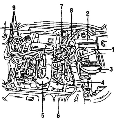
Figure 15. Location of individual removable or disconnectable parts of the XU-type engine. References to numerical designations are given in the text.
2.1.3 Removing the power unit - XU engines
Despite the differences between individual engine types, this section describes all XU-group engines. The powertrain is removed as a single unit. This job requires a strong lifting device, but the engine can be removed with two strong helpers. To remove the engine, the front of the car must be placed on stands. In the following text, the description of removal is given in general terms, since it is impossible to give a description for each individual engine in all details. Depending on the model, some work may need to be adjusted.
Figure 15 shows the engine compartment with an 8-valve engine. The purpose of the drawing is only to give an idea of the arrangement of individual parts.
- Remove the decorative wheel covers (removing one bolt on each wheel). Tighten the handbrake and loosen the drive shaft nuts with the appropriate wrench head, without unscrewing the nuts, as shown in Figure 7.
- Disconnect the wires from the battery and remove the battery (1).
- Remove the ignition system control unit (2).
- Remove the battery bracket (underneath it is the engine mount).
- Remove the hoses and tubes (4) and (5) belonging to the air intake system.
- Disconnect the following parts at the indicated locations: Throttle cable (6), speedometer flexible shaft (7), brake booster vacuum hose (8) and fuel lines (9).
- Find all electrical wires and disconnect the connectors. Move the wires to the side so that they do not interfere with the removal of the power unit.
- After this, remove the wheels and unscrew the wheel arch liners.
- Remove the radiator. The lower hose has a special fastener, and to disconnect it, refer to the "Cooling System" section. Both heater hoses also have a special fastener. Figure 16 shows the locking bar that should be pulled out first. After this, use a screwdriver to press the tab (1) in Figure 17 to the right and at the same time sequentially pull the hoses off their fittings.
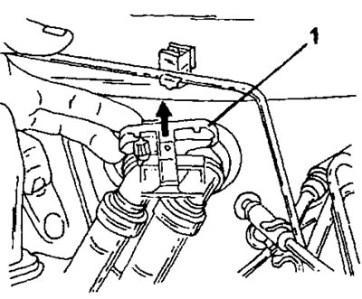
Figure 16. Pull the retaining bar (1) in the direction of the arrow upward to disconnect the heater hoses from the bulkhead.
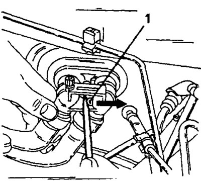
Figure 17. Fastening the heater hoses to the fittings. The hoses are removed only after pressing the tab in the direction of the arrow.
- Drain the oil from the gearbox and axle reducer. The oil is drained from the engine if work on the engine is planned that requires draining the engine oil from the engine.
- Loosen the nuts from below that connect the exhaust manifold to the front pipe of the exhaust system. Remove the released springs and washers. Release and lower the front pipe.
- Disconnect the three gear shift rods from the gearbox.
- Raise the front of the car and place strong stands under the body. Turn the wheels away. The wheel suspensions should hang freely.
- To remove the power unit, it is necessary to set the engine compartment hood in a vertical position. Since holding the hood in this position requires a special tool, it is best to unscrew the hood and set it aside in a safe place. To do this, mark the contours of the hinges on the hood with a pencil and unscrew the hinge bolts. While unscrewing the last bolt, have an assistant hold the hood.
- Unscrew the two bolts (1) and (2) in Figure 18 and pull out the reaction support (3).
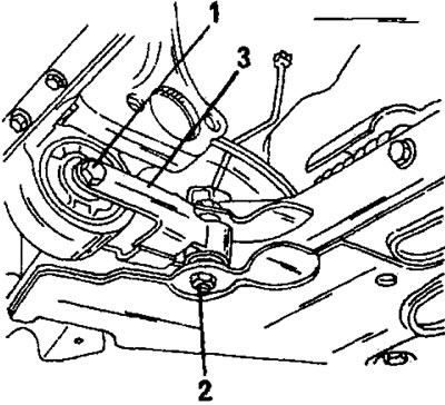
Figure 18. Installed reaction support 1. Bolt, 50 Nm; 2. Bolt, 70 Nm; 3. Reactive support
- Press the right and left ball joints out of the steering knuckles as described in the section "Front wheel suspension". The connection between the steering knuckle and the ball joint journal is secured with a tie bolt.
- Remove both drive shafts in accordance with the instructions in the relevant section.
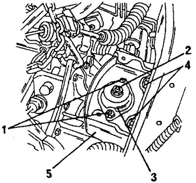
Figure 19. Suspension mount from the gearbox side. 1. Nuts, 20 nm; 2. Nut, 65 nm; 3. Rubber-metal support; 4. Nuts, 25 nm; 5. Suspension beam
- Disconnect the electrical wires from the gearbox (for example, the starter wire and the reverse light switch wire).
- Disconnect the vacuum hose from the brake booster.
- Attach the power unit to a crane or other suitable lifting device using chains or cables and slowly pull the power unit until the chains or cables are taut.
- Once again, make sure that all connections are made, lift the power unit and remove it from the engine compartment. At the same time, constantly ensure that tubes, hoses, wires, etc. do not get caught on the power unit and that all disconnections are made.
- After removal, place the engine on a suitable support, such as a wooden block, and secure the power unit from tipping over. After this, inspect the entire power unit for external damage and leaks, such as traces of oil, which may indicate damaged parts. After this, clean the outside of the engine. Cover all sensitive parts.
2.1.4 Installing the power unit - XU engine
The power unit is installed in reverse order. The general instructions given for the TU engine also apply to this engine. However, the left, right and rear engine/gearbox mounts look different.
- Lower the power unit to the desired position until the engine mount is level and install the engine support on the left side (looking at the car from the front). The support is shown in Figure 20. Tighten all engine mount bolts to 45 Nm.
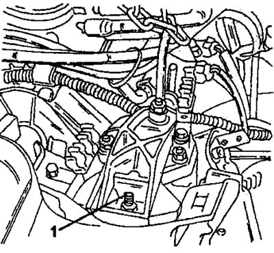
Figure 20. View of the suspension from the timing drive side on an XU-type engine. The nut (1) is tightened to a torque of 45 Nm.
- Install the suspension support (5) on the other side of the vehicle and tighten the bolts (4) to a torque of 25 Nm.
- Raise the engine mount enough to fit the engine mount onto the stud and tighten both nuts (1) to a torque of 20 Nm. Then tighten the center nut (2) to a torque of 65 Nm.
- Connect the clutch cable.
- After this, install both drive shafts in accordance with the instructions in the relevant section.
- Restore the connection of the ball joints with the steering knuckles. To do this, the transverse lever is pressed upward so that the support tip enters the steering knuckle. Tighten the tie bolt and nut to a torque of 40 Nm. Work on both sides.
- Install the rear suspension of the power unit using Figure 18. After placing the reaction support in the position shown in the figure, tighten bolt (1) to a torque of 50 Nm and bolt (2) to a torque of 70 Nm.
- All unmentioned works are carried out in reverse order without any particular difficulties.