



Table of contents: 2.3.1 TU Engines 🠇 2.3.2 Assembly of XU10 type engines 🠇 2.3.3 XU7 type engines 🠇
The following general guidelines apply to all engine types:
- Before assembly, check that the parts are clean and free of foreign inclusions.
- Apply a layer of grease to all rotating and moving parts. This should be done before assembly, not after, as this will prevent the lubricant from reaching the areas where the parts come into direct contact. It is especially important to generously lubricate the pistons, piston rings, and cylinder walls with engine oil.
- Thoroughly clean all cylinder block parts if the engine has been completely disassembled. When partially disassembling, do not allow foreign objects to enter the disassembled engine parts or cavities. To avoid this, all holes should be either sealed or covered with rags.
- It is best to blow out lubrication channels and lubrication holes with compressed air. If there is no compressed air line, clean the lubrication channels and lubrication holes with a wooden stick, under no circumstances using metal objects. Under no circumstances should you skimp on parts or reinstall parts that were initially damaged.
- The size and adjustment tables provide wear limits for most moving parts. In case of doubt or when approaching the wear limit, it is recommended to replace the part, saving on another engine disassembly in the near future,
- All spare parts should be purchased only from Peugeot dealerships, indicating the engine number. Since modernisation and consequent modification of individual parts are constantly taking place, only the Peugeot supplier is able to select the required spare part.
- Before starting the actual assembly, on some engines it is necessary to measure the protrusions of the cylinder liners. At the base of the working cylinder liners there are circular cross-section sealing rings, which, however, do not have any effect on the size of the liner protrusion. The protrusion size corresponds to the specified value in almost all cases, but for reliability it should be measured. The O-rings are located in the locations shown in Figure 54.
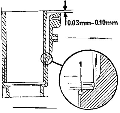
Figure 54. The O-ring (1) is inserted in the indicated location.
The dimensions of the protrusions are checked as follows:
- Insert the assemblies of cylinder liners, pistons and connecting rods without O-rings into the cylinder block. Ensure that the markings on the working liners and pistons match and that the arrows on the piston crowns point towards the front of the engine, i.e. towards the timing drive (Figure 55).
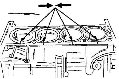
Figure 55. Marking the position of the working cylinder liners in relation to the cylinder block.
- Measure the height of the protrusion of each cylinder working liner with a depth gauge or using a special measuring block, shown in Figure 56. First, measure the height of the protrusion of the working liner of each cylinder above the surface of the cylinder block, and then measure the difference in protrusions for all two adjacent working liners. The difference in the protrusion of two adjacent cylinder liners should not exceed 0.05 mm. The cylinder liners should protrude above the cylinder block surface within 0.03–0.10 mm. Measurements of the cylinder liners should be taken on both sides of the cylinder block.
- Remove the cylinder liners again and install the O-rings in the locations shown in Figure 54 without turning the rings. When installing new cylinder liners, mark all four liners in accordance with Figure 55.
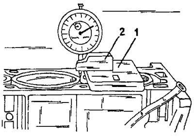
Figure 56. Checking the size of the cylinder liner protrusion using a special measuring board (1) and a pointer indicator (2) on the stand.
After this, the engine can be assembled in the following sequence.
2.3.1 TU Engines
- Assemble the pistons and connecting rods according to the instructions in section 2.5.3.
- Install the pistons into the cylinder liners as described in the section for these engines.
- Insert the cylinder liners assemblies in accordance with the cylinder numbers marked after measuring the protrusions (Figure 55) into the cylinder block and press them down well. Secure all working sleeves with clamps. Under no circumstances should the cylinder liners or pistons be allowed to fall out of the cylinder bores when the engine is turned over.
- Insert the connecting rod bearing shells into the connecting rods according to the markings (when installing the previous parts). The guide tabs of the bearing shells must fit into the cutouts in the connecting rod holes.
- Insert the main bearing journals with lubrication holes into holes No. 2 and No. 4, and insert the remaining simple bearing shells without lubrication holes into holes No. 1, 3 and 5. Ensure that the projections of the shells fit into the cutouts of the bearing holes.
- Apply both crankshaft end play adjusting half washers to each side of the second crankshaft main bearing. The lubrication holes of both halves of the washers must face outward on each side, that is, towards the crankshaft cheeks. Lubricate the washers well with engine oil. Figure 57 shows the arrangement of the parts.
- Carefully insert the crankshaft into the bearing shells. The working surfaces must be well lubricated with engine oil. To do this, use an oiler and rub the oil in with your finger; do not use a brush to apply the oil.
After this, check the axial play of the crankshaft:
- Install a dial indicator on a suitable stand at the front of the engine and attach the measuring probe to the crankshaft boss, as shown in Figure 58. If the dial indicator has a stand with a magnet, the stand can be installed on the shaft and the measuring probe can be attached to the ground surface of the block.
- Press the crankshaft with a screwdriver in one direction and reset the dial indicator scale to zero.
- Press the crankshaft in the other direction and read the reading from the dial indicator scale. The value should be within the range of 0.10 - 0.30 mm.
- If the axial play exceeds the specified tolerance, two oversized half washers must be installed. Both washers must be the same thickness. In addition to the standard 2.40 mm size, larger washers are available: 2.50, 2.55, and 2.60 mm. It's important to ensure both washers are of equal thickness to prevent the crankshaft from being forced to one side.
- Install the connecting rod bearing caps together with the bearing shells. Make sure that the bearing shells are installed in the correct connecting rods. The cylinder numbers applied during disassembly must be located on the connecting rod and on the connecting rod bearing cap on the same side. To install two connecting rod bearings for mounting from the top side, rotate the crankshaft accordingly.
- Screw the nuts onto the connecting rod bearing studs and tighten to a torque of 40 Nm.
- Place the bearing shells into the lower half of the engine crankcase. Insert two bearing shells into the holes of the intermediate bearings (No. 2 and No. 4), as shown in Figure 59. The bearing shells must be well lubricated with engine oil. To do this, use an oiler and rub the oil in with your finger; do not use a brush to apply the oil.
- Hammer a key into the front end of the crankshaft and, using a piece of pipe, press the oil pump drive pulley onto the crankshaft without pressing out the key. Engage the drive chain with the sprocket.
- Cover the contact surface of the lower half of the engine crankcase with sealing compound. You can inquire about the type of sealant at your Peugeot service center. A sealant is a substance that remains soft even after drying.
- Place the lower half of the engine crankcase on the cylinder block without moving the bearing shells. Tap the crankcase into the desired position with a rubber hammer.
- Screw in the bolts (10 pieces) one at a time and tighten them to a torque of 20 Nm in several passes, working from the center outward. From this position, tighten the bolts in the same sequence to a 45° angle without using a torque wrench.
- Install the oil pump on the bottom of the engine crankcase. At the same time, engage the drive chain with the pump sprocket. Tighten the bolts with a tightening torque of 8 Nm.
- Cover the contact surface with the oil pan with sealing compound and place the oil pan on the engine crankcase. Screw in 19 bolts and tighten them evenly around the circumference to a torque of 8 Nm.
- Install the small bolts along the connecting flange between the cylinder block and the lower half of the engine crankcase and tighten them evenly to a torque of 8 Nm. Simultaneously, tighten the switch next to the oil filter flange to a torque of 28 Nm, and tighten the switch located above it to a torque of 25 Nm. Tighten the bolt located next to the engine number to a torque of 40 Nm. Install the oil filter with a new gasket. The filter is tightened with a torque of 14 Nm, but this value is approximate, since it is impossible to install a torque wrench in this case,
- Using a suitable piece of pipe, press the seal into place on the flywheel side. When pressing in, the seal must not be deformed. On the same side, screw in the plug of the main lubrication channel and tighten it with a rod wrench to a torque of 30 Nm,
- Install the flywheel on the crankshaft. At the same time, turn the flywheel on the crankshaft flange until all holes are aligned. The bolts must be replaced. Cover the bolt threads with locking compound. When tightening the bolts, lock the flywheel as shown in Fig. 60. Tighten the bolts evenly to a torque of 65 Nm.
- Place the driven clutch disc into the flywheel and install the clutch basket. The long side of the driven disc hub must face outward. Turn the drive disk until both markings align (when reinstalling the old parts) and screw in the bolts. A centering shaft is required to install the clutch. This work operation is described in detail in the "Clutch" section. Hold the flywheel in place as described above and tighten the bolts crosswise to 15 Nm. Check the free axial movement of the centering shaft.
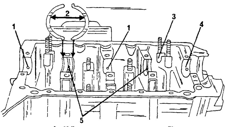
Figure 57. Installing the crankshaft on a TU type engine. 1. Conventional bearing shells; 2. Accelerating washers; 3. Connecting rod bearing shells; 4. Conventional bearing shell; 5. Bearing shells with lubrication holes
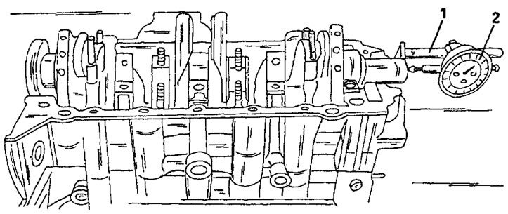
Figure 58. Measuring the axial play of the crankshaft. 1. Dial indicator stand 2. Dial indicator
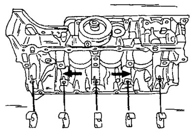
Figure 59. Inserting main bearing shells. Two liners with lubrication holes are installed in the holes marked with arrows.
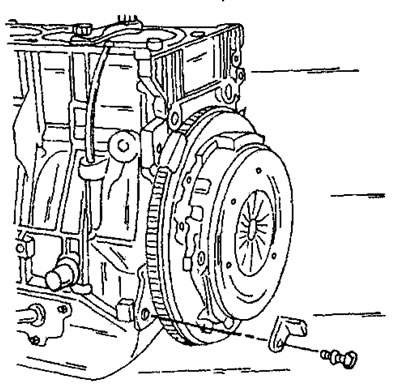
Figure 60. Using a stopper to lock the flywheel when loosening the clutch, flywheel and crankshaft belt pulley.
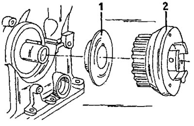
Figure 61. Details from the front side of the crankshaft. 1. Metal washer; 2. Crankshaft toothed pulley
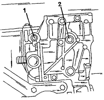
Figure 62. Tighten bolts (1) and (2) to the tightening torques specified in the text.
- Press the oil seal into the front of the cylinder block. Here, too, first lubricate the sealing lips of the oil seal with oil and carefully hammer the oil seal into the hole without deforming it. It's best to first tap the seal with a hammer until it's about 1 mm in. Then, using a pipe of the appropriate diameter, drive the seal in until its outer surface is flush with the cylinder block surface. After this, tighten the plug of the main lubrication channel with a tightening torque of 30 Nm.
- Place washers (1) and crankshaft toothed pulley on the front side of the crankshaft (Figure 61). Replace the bolt and tighten it to 110 Nm. The flywheel must be locked again. Working from this side of the cylinder block, insert an O-ring into the groove. Also temporarily secure the timing belt tension roller with a nut.
- Install the water pump on the cylinder block. The bolts are tightened to different torques. Two bolts (1) (Figure 62) tightened to a torque of 30 Nm, and the bolt (2) to a torque of 55 Nm.
- Place the ignition timing scale on the flywheel side of the engine and tighten the two bolts to a torque of 8 Nm.
- After this, insert the bent pin into the flywheel through the engine crankcase. Before doing this, turn the flywheel accordingly so that the pin can be inserted. In this case, the flywheel is set to the position for adjusting the valve timing mechanism. The hole for the pin is located on the left side, slightly below the engine number. Figure 63 shows the pin inserted into the engine.
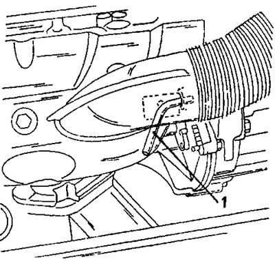
Figure 63. The crankshaft locking pin is inserted in the indicated location
Loosen the clamping strips of the cylinder liners. Place the unlubricated cylinder head gasket on the cylinder block over both dowel pins. The manufacturer's mark (1) in Figure 64 must be visible from above after the gasket has been applied. The tongue 92) must be located on the clutch side. Please note that the cylinder head and its gasket may be marked with the letter "R." This marking will be discussed in more detail when describing the cylinder head. When purchasing a gasket, be sure to ask for the correct option. Both centering pins (3) must be located in the cylinder block.
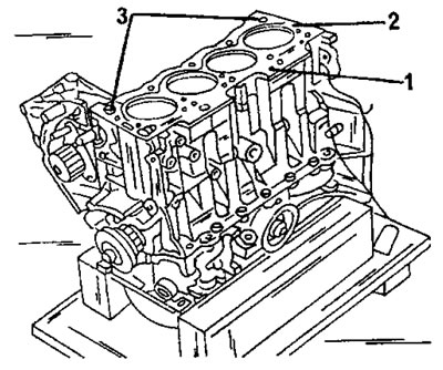
Figure 64. Applying the cylinder head gasket. 1. Manufacturer's mark; 2. Tongue; 3. Centering pins
Lower the cylinder head onto the cylinder block. For this purpose, the two bent levers mentioned during removal can be used again. The position of the camshaft does not play a role. Place the cylinder head on both centering pins and tap it with a rubber hammer. Subsequent work on installing the cylinder head is carried out both on the engine removed and on the engine installed on the vehicle:
- Turn the camshaft like this. so that the locking pin can be inserted from the front side of the camshaft timing pulley as shown in Figure 65. This will position the camshaft in the position required for installing the timing belt. To install the pin, move the toothed pulley in different directions until the pin is installed.
- Place the assembled rocker arm shaft on the cylinder head so that the centering pins enter, as shown in Figure 66. Tap the rocker arm shaft well with a rubber hammer so that all four bearings sit on the centering pins.
- Lubricate the threads and the undersides of the cylinder head bolt heads with engine oil. Screw in and tighten the cylinder head bolts by hand. The cylinder head bolts are tightened according to the diagram in Figure 67, but a protractor is required to tighten the bolts to a certain angle. Usually a special tool is used for this work (Figure 35), but you can also make a round disk yourself and divide it into three 120° sectors. Since tightening is done at an angle of 120° or 240°, one or two sectors can be used for tightening.
On an engine with an aluminum cylinder head:
- Tighten all bolts in the sequence shown in Figure 67 to a torque of 20 Nm.
- Once the bolts are tightened, remove the torque wrench and place a protractor on the wrench head. If using a homemade dividing disc, cut a square in its center to accommodate the wrench handle extension. Place the extension with the socket on the wrench head and align the "zero" on the protractor with the reference point on the cylinder head.
- In the sequence of the diagram in Figure 67, tighten each bolt until the 240° sector on the protractor scale coincides with the reference point on the cylinder head.
- After tightening the bolts in the manner described, their subsequent tightening on a warm engine, as was the case with previous engine models, is no longer required.
On an engine with a cast iron cylinder head:
- Tighten all bolts in the sequence shown in Figure 67 to a torque of 20 Nm.
- The bolt tightening method is different from the engine with an aluminum cylinder head. If a homemade dividing disk is used, it should be divided into three sectors here.
- Once the bolts are tightened, remove the torque wrench and place a protractor on the wrench head. In the sequence of the diagram in Figure 67, tighten each bolt until the 120° sector on the protractor scale coincides with the reference point on the cylinder head.
- After tightening the bolts as described, they should be tightened by another 120° in the sequence shown in Figure 67. The protractor remains in its original position and the bolts are tightened until the 240° sector coincides, or you can start from zero and tighten the bolt to the 120° mark on the scale.
- After this, the toothed belt is installed. Please note that a special device is required to tension the belt. This device consists of a lever and a weight. To set the roller to the required position, the lever is inserted into the hole in the belt tension roller, and a load is suspended from the cord. It is important to follow the instructions carefully, as incorrect timing belt installation can be costly. It is absolutely necessary to obtain such a device. As mentioned during removal, an experienced mechanic can set the timing belt tension using a spring balance if the belt tension was measured before removal. You should also read section 2.8.4. It provides a brief description of how to use this device if you can rent it. When using it, perform the work as follows:
Inspect the belt from the outside and find the direction arrow (see Figure 68). Place the belt so that the arrows on it point in the direction of belt movement. Check that both locking pins are inserted and apply the timing belt as shown in Figure 68. First, apply the belt to the crankshaft timing pulley, then to the camshaft timing pulley, and then to the water pump pulley. Finally, the belt is placed on the tension roller with your fingers, as shown in the figure. Check the engagement of the belt teeth with the teeth of all pulleys.
Insert the special device shown in Figure 69 into the square hole of the tension roller and tighten the nut in the middle of the tension roller.
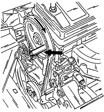
Figure 65. Insert the locking pin from the indicated side into the camshaft sprocket.
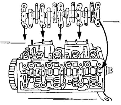
Figure 66. Installing the rocker shaft. The arrows indicate the position of the centering pins.
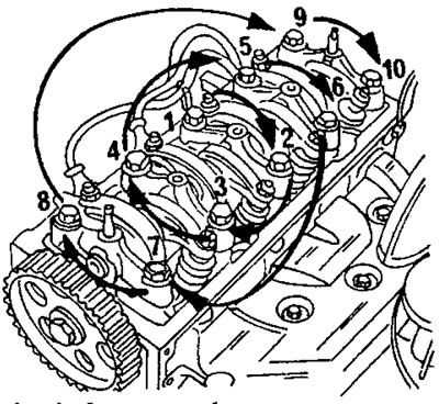
Figure 67. Cylinder head bolt tightening diagram for a TU engine (with or without working cylinder liners).
- Remove the locking pins from the camshaft timing pulley and from the rear of the engine case to unlock the engine.
- Turn the crankshaft one revolution. Rotate the shaft only in the direction of working rotation. Reinsert the pin into the flywheel to reset it to its original position.
- Loosen the tension roller nut. Press the toothed belt with your finger from the rear side as shown in Figure 70.
- At the same time, the lever rises and remains in this position. Check that the camshaft has not turned and insert the locking pin into the hole in the toothed pulley. If the pin does not fit, the toothed pulley has turned. Tighten the nut to 20 Nm and remove the pin from the flywheel.
- Turn the crankshaft one more revolution to the right to a position where the 6 Nm pin can be inserted again.
- Slowly loosen the tension roller nut. Rapidly loosening the nut will cause the load to drop quickly, meaning the nut must be loosened gradually. After lowering the load to its bottom position, tighten the nut again to a torque of 20 Nm.
- Re-insert both locking pins into the flywheel and camshaft sprocket to check the valve timing, and then remove the pins. After this, you can remove the timing belt tensioner.
- Install the crankshaft belt pulley housing.
- Install the alternator belt pulley if it was removed without removing the entire alternator. Tighten the bolts to a torque of 8 Nm.
- Adjust the tension of the generator drive belt using Figure 71. To do this, turn the bolt (1) until the required tension is achieved. After this, tighten the bolt and nut (3) to a torque of 15 Nm, and the bolt and nut (2) to a torque of 35 Nm.
- Install both covers (4) and (5) (Figure 72).
- In accordance with the instructions in section 2.4.5, adjust the valve clearances and then install the oil deflector plate (1), two spacers (2) and the cylinder head cover (3) (Figure 72). Install the oil dipstick tube (6) and secure with a bolt. The cylinder head cover bolts are tightened with a tightening torque of 5 Nm.
- All other work is carried out in reverse order.
2.3.2 Assembly of XU10 type engines
To thoroughly clean the cylinder block, unscrew the plugs of the main lubrication channel to flush the holes. The plugs are located on the back side (tightening torque 48 Nm) and from the cylinder block side (tightening torque 25 Nm). To remove the plugs, you will need a socket head cap wrench.
Secure the cylinder block to a mounting stand or place it on a workbench (crankshaft side up) and insert the upper bearing shells. In this case, the following points should be taken into account:
- Although the bearing shells are identical, they should be installed in accordance with the markings made during removal.
- Since December 1993, the main bearing clearance on XU10 engines has been reduced. Please check whether this modification applies to your vehicle (engines are also installed on other car models). The reduction in backlash is achieved by using four different classes of bearing shell sizes in the bearing caps (instead of one single size). The cylinder block liners have a lubrication groove and are available in only one size. If selective bearing shells are installed, the crankshaft at location "a" in Figure 73 is marked. The same marking is applied in place of "B" on the cylinder block. However, selecting bearing liners is not easy and requires qualified advice. It is best to contact a service station. With the introduction of new bearing shells, the oil pump drive has also changed.
- Lubricate the inserted bearing shells thoroughly with engine oil (check if they have lubrication grooves). Also lubricate the journals of the main and connecting rod bearings with engine oil and place the crankshaft in the block. Turn the crankshaft several times to seat the bearing shells.
- Insert half washers behind the second bearing to remove the axial play of the crankshaft. The sides of the washers with lubrication grooves must face the crankshaft cheeks. These are half washers without "guide tabs".
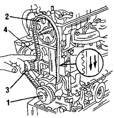
Figure 68. Applying the toothed belt. Place the belt on the pulleys in numerical order. The cutout shows the direction of movement of the toothed belt.
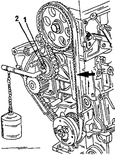
Figure 69. Timing belt tensioner mounted on a tension roller.
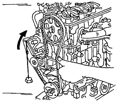
Figure 70. To move the lever with the load to the upper position, press the toothed belt with your finger.
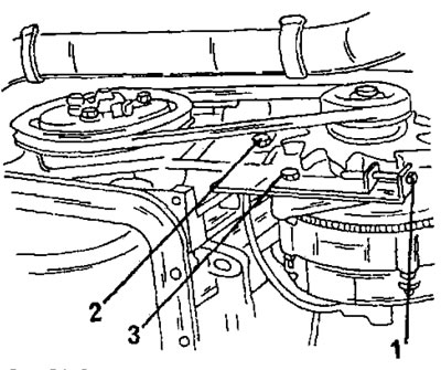
Figure 71. Adjusting the alternator drive belt tension. 1. Tension bolt; 2. Mounting bolt; 3. Mounting bolt
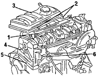
Figure 72. Installing the cylinder head cover. The explanation of digital designations is given in the text.
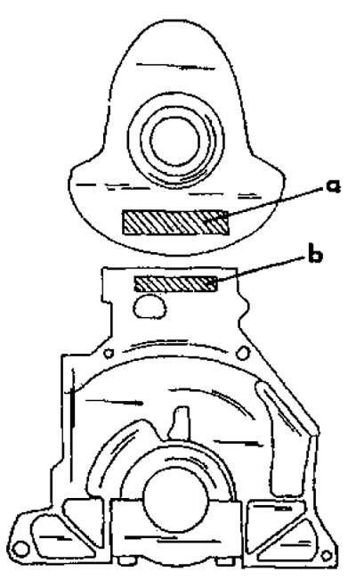
Figure 73. If a modified crankshaft is installed, there are markings in the indicated locations.
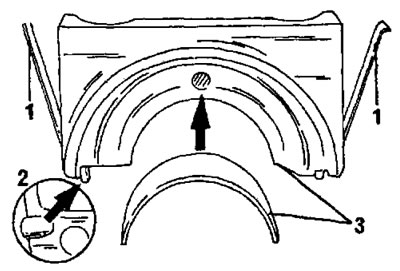
Figure 74. Installing bearing caps. 1. Side seals; 2. Centering pin; 3. Pay attention to the markings on the cover and bearing shell
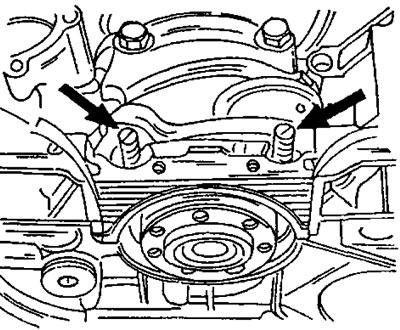
Figure 75. Installing the rear main bearing cap. The arrows indicate two screwed-in studs. Two aluminum strips are visible on the left and right.
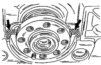
Figure 76. Cover the indicated areas on the surface of the cover plate with sealing compound.
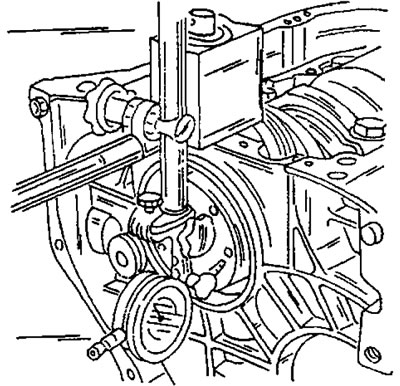
Figure 77. Checking the crankshaft axial play.
Insert liners that do not have lubrication grooves. Place both remaining half washers near the second bearing. the "guide tabs" should fit into the cutouts (Figure 53).
Place the bearing caps in accordance with the markings and start working. First install bearing caps 1, 2, 3 and 4 and tighten them slightly. There are centering pins on the bottom of the covers that should fit perfectly (Figure 74).
The flywheel side bearing cap has side seals, which are visible in Figure 74. Service stations use a special tool to install the seals. Seals can be installed in the following way:
- Insert both sealing liners into the bearing cap with the sealing grooves facing outward, so that they protrude from the underside by approximately 0.2 mm. Lubricate the sealing liners and the bearing cap thoroughly with engine oil and insert the bearing liners into the cap.
- Instead of the bearing cover bolts, screw in two studs with a slot for a screwdriver at the end, in accordance with Figure 75, cover the places indicated in Figure 76 with sealing compound and install the bearing cover. Place two strips of aluminum foil between the sealing liners and the cylinder block and carefully tap the bearing cap. Constantly check that the sealing inserts have not moved.
- Remove the aluminum foil and unscrew the studs, then tighten the bearing cap bolts. After this, tighten the bearing cap bolts evenly from the inside outward to a tightening torque of 70 Nm. After tightening the bolts, turn the crankshaft several times (by screwing two bolts into the flange and inserting a metal rod between the bolts). If the crankshaft is slightly jammed, tap the bearing caps.
- Using a sharp knife, cut the protrusions of both sealing inserts flush with the block surface.
- After this, the axial play of the crankshaft is measured. To do this, install the dial indicator as shown in Figure 77, resting the measuring probe against the crankshaft flange and moving the crankshaft in both directions with the handle of a hammer. The dial indicator reading should not exceed 0.07–0.32 mm. If necessary, replace the bearing washers on the second bearing with larger washers. Washers of various increased sizes are available (1.95, 2.00 and 2.05 mm).
- Press the oil seal from the rear side without damaging it.
- Install the pistons and connecting rods following the instructions in the appropriate section.
- Install the flywheel. Be sure to install new flywheel mounting bolts. The installation position of the flywheel is determined by the centering pin at the end of the crankshaft. First check whether the plug is screwed into the cylinder block (tightening torque 48 Nm). Tighten the flywheel mounting bolts evenly and crosswise to a torque of 50 Nm. While doing this, hold the crankshaft from turning. Install a small plate with a new gasket onto the flywheel and tighten both bolts (6 nm).
- Check the flywheel runout after installation. To measure, install the dial indicator as shown in Figure 77. The measuring probe is installed on the flywheel surface. When turning the flywheel/crankshaft, observe the readings on the dial indicator scale. The dial indicator reading should not exceed 0.06 mm per revolution. Higher readings may be caused by foreign objects lodged between the flywheel and the crankshaft.
- If the belt tensioner support pin was removed, lubricate the threaded portion with locking compound and tighten the pin into the cylinder head with a tightening torque of 16 Nm. Install the belt tensioner and hand-tighten the bolt. On a 16-valve engine, also install a second belt tensioner.
- Install the oil pump on the other side of the cylinder block. The sprocket is installed together with the drive chain in accordance with Figure 51. Do not forget to place a spacer plate between the pump and the cylinder block. Tighten the three bolts to a torque of 13 Nm. The three bolts have different lengths. The longest bolt (length 80 mm) is placed on the right side, and the shortest one (65 mm) is placed on the left side. The third bolt has a length of 70 nm.
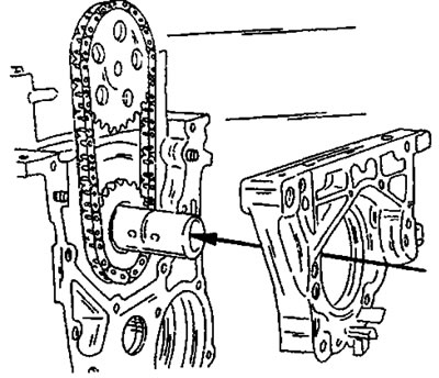
Figure 78. Installing the front cover. Cover the cylinder block surface with sealing compound.
- Install the front cover in the manner shown in Figure 78. Pre-coat the cylinder block surface with sealing compound (Forma Joint). Insert two 40 mm long bolts from below and two 20 mm long bolts from above. Tighten the bolts to a torque of 16 Nm.
- Press the front oil seal into the cover. The seal has a small oil reservoir that must be installed in the correct position. The seal has a marking on the outside as shown in position (2) in Figure 79. Position the seal so that the marking is located opposite the journal in the cover. Lubricate the sealing lips of the oil seal and its outer side with engine oil and drive the oil seal in using a piece of pipe of the appropriate diameter.
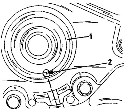
Figure 79. Installing the front crankshaft oil seal (1). The marking (2) must be located in line with the journal.
After this, it is necessary to install the oil pan. There are two possible options:
- If the vehicle is equipped with air conditioning, cover the contact surface with sealing compound (Auto Joint) and install the oil pan. Fasten the oil pan in accordance with Figure 80. Pay attention to the location of the individual bolts. Tighten all bolts to a torque of 16 Nm.
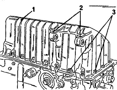
Figure 80. Fastening the oil pan on a vehicle with air conditioning. 1. Bolts 22 mm long (19 pieces); 2. Bolts 40 mm long (2 pieces); 3. Bolts 20 mm long (2 pieces)
- When installing a conventional oil pan, apply a new oil pan gasket and apply compound to the cylinder block surface. The bolts are tightened to a torque of 16 Nm, but the length of the bolts is not the same. The two center bolts on the narrow sides of the oil pan and the center bolt on the long side are 16 mm long. The remaining bolts are 20 mm long. Be careful not to mix up the bolts.
- Place a new gasket on the cylinder block and tighten the water hose with a tightening torque of 18 Nm (2 bolts).
- Install a new water pump gasket, install the pump, and tighten the 5 bolts to a torque of 15 Nm. Replace the plug opposite the water pump and tighten to a torque of 48 Nm. The plug must be replaced after removal.
- Install the engine mount bracket. The bracket is secured with 5 bolts with a tightening torque of 60 Nm. Coat the bolt threads with Frenbloc locking paste.
- Screw in the oil pressure sensor (25 Nm) or plug (32 Nm) from the other side of the cylinder block. The plug above the sensor/plug is tightened to a torque of 25 Nm.
- Lubricate the gasket of the new oil filter with engine oil and screw the filter into the engine until it fits tightly. From this position, tighten the filter manually another three-quarters of a turn.
- Install the cylinder head according to the instructions given for the 8 or 16-valve XU10 engine or for the XU7 engine.
- On an 8-valve engine and on an XU7 type engine, set the valve clearances in accordance with the instructions given below. For the exhibition, a toothed pulley must be put on the camshaft (to turn the camshaft) and after the exhibition it was removed again.
- Lubricate the outside and sealing lips of the new oil seal with engine oil and press the new oil seal into the cylinder head. In this case, use a piece of pipe of the appropriate diameter. After installing the oil seal, place the toothed pulley on the camshaft and secure it with a bolt and washer. Tighten the bolt to a torque of 35 Nm. The toothed pulley must be held in place as shown in Figure 81.
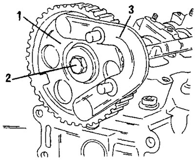
Figure 81. Holding the camshaft from turning on an XU10 engine. 1. Timing pulley of the camshaft; 2. Bolt; 3. Locking device
- Install and tension the timing belt following the instructions in the appropriate section for the specific engine type. Please note that this requires locking pins to lock the crankshaft and timing pulley (8-valve engine) or toothed pulleys (16-valve engine). In addition, a special device for tensioning the toothed belt is required.
- Secure the lubrication system pipe to the middle of the cylinder head and put on the cylinder head cover. The bolts are located in the places shown in Figure 47 and tightened to a torque of 10 Nm. Tighten the spark plugs (18 Nm).
- Install new exhaust manifold gaskets and tighten the 8 nuts crosswise to a tightening torque of 35 Nm.
- Coat the end of the oil dipstick tube with Frenbloc locking compound and insert the tube into the cylinder block. Tighten the bolt at the top end to 10 Nm.
- Install the intake manifold pipe on the other side with a new gasket. Tighten two nuts to a tightening torque of 30 Nm and four bolts to a tightening torque of 22 Nm.
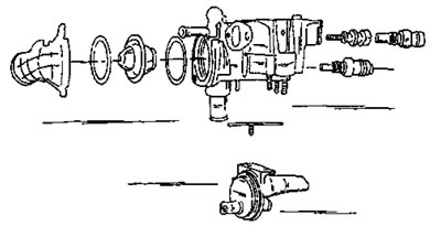
Figure 82. Thermostat housing parts. Three temperature sensors are tightened with a tightening torque of 18 Nm.
- The thermostat housing has the parts shown in Figure 82. Replace the O-rings and the sealing washer of the upper bolt (having a head with an internal hexagon). Tighten the three temperature sensors to a torque of 18 Nm, as well as the two housing cover bolts.
- Install the assembled thermostat housing onto the cylinder head at the end of the camshaft. Cover the contact surface of the cylinder head and thermostat housing with sealing compound (Forma Joint). Tighten the bolts evenly to a tightening torque of 13 Nm, while observing the bolt arrangement;
- One bolt is located on the inside of the housing.
- Three bolts are 40mm long and are located around the housing hole (where the end of the camshaft is visible).
- One bolt is 55mm long and is located at the bottom right.
- One bolt is 75mm long and is located on the left side. To avoid making mistakes, study Figure 83.
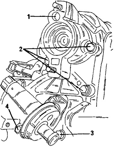
Figure 83. Fastening the distributor drive housing. 1. = 13 nm; 2. =13 nm, 40 mm; 3. = 13 nm, 55 mm; 4. = 13 nm, 75 mm
- Install the ignition distributor in accordance with the markings made during removal. A new O-ring must be installed. Place a vacuum hose on the distributor fitting, connect a larger hose underneath it, and connect another hose a little to the left. Install the spark plug wire guide and put on the distributor cap. Tighten both bolts (15 Nm).
2.3.3 XU7 type engines
- It is assumed that the cylinder liners have already been measured as described in section 2.3.1 for TU type engines.
- Assemble the pistons and connecting rods as described in section 2.5.3.
- Install the pistons into the cylinder liners as described in section 2.5.3.
- Insert the cylinder liners into the cylinder block in accordance with the cylinder number markings made after measuring the liner protrusions and press the liners down firmly.
- Secure all working sleeves with clamps. Under no circumstances should the cylinder liners or pistons be allowed to fall out of the cylinder bores when the engine is turned over.
- Insert the connecting rod bearing shells into the connecting rods according to the markings (when installing the previous parts). The guide tabs of the bearing shells must fit into the cutouts in the connecting rod holes.
- Insert the main bearing shells with lubrication grooves into the holes. The guide tabs must fit into the bearing hole cutouts. It should be taken into account that some bearing liners have lubrication grooves, while others do not. To avoid mistakes, it is better to label the inserts. Ensure correct installation of bearing shells.
- Insert the spacer washers into bearing No. 2 (bearing No. 1 is located on the clutch side) with the sliding side facing the crankshaft.
- Generously lubricate the bearing shells with engine oil and insert the crankshaft into the shells. To lubricate, use an oil can and rub the oil in with your fingers. Do not use a brush for this.
- Insert new side sealing rings into bearing cap No. 1. Install the cap with the bearing shells generously lubricated. In this case, the side seals may shift. To avoid this, you can insert two feeler gauges between the seals and the engine crankcase and then install the cover. After this, pull out the probes.
- Reinstall the remaining bearing caps with the inserted liners (the spacer washers in bearing cap #2) in their original positions. The bearing caps are numbered and the lug should face the timing drive.
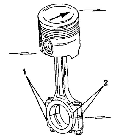
Figure 84. When installing the parts shown, ensure the correct orientation of the pistons and connecting rods. 1. Mark on the connecting rod and on the bearing cap; 2. Grooves on bearing caps
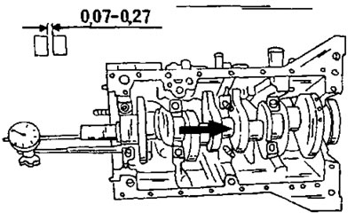
Figure 85. Measuring the axial play of the crankshaft.
Tighten the main bearing cap bolts in sequence to the specified torque.
After this, weld the axial play of the crankshaft as follows:
- Install a dial indicator on a suitable stand at the front of the engine and attach the measuring probe to the crankshaft boss, as shown in Figure 85. If the dial indicator has a stand with a magnet, the stand can be installed on the shaft and the measuring probe can be attached to the ground surface of the block.
- Press the crankshaft with a screwdriver in one direction and reset the dial indicator scale to zero.
- Press the crankshaft in the other direction and read the reading from the dial indicator scale. The value should be within the range of 0.07 - 0.27 mm.
- If the axial play exceeds the specified tolerance, two oversized half washers must be installed. Both washers must be the same thickness. In addition to the standard 2.30 mm size, larger washers are available: 2.35, 2.40, 2.45, and 2.50 mm. It's important to install both washers of the same thickness to prevent the crankshaft from being forced to one side.
- Check how far the seals on bearing cover No. 1 protrude above the surface of the cylinder block. If they protrude more than 2.0 mm, they should be trimmed accordingly with a sharp knife.
- Install the connecting rod bearing caps together with the liners. When reinstalling, ensure that the bearing shells are installed together with the corresponding connecting rods. The cylinder numbers applied during disassembly must be located on the same side.
- Tighten the connecting rod bearing nuts in sequence. Tighten the nuts of each connecting rod alternately to the specified tightening torque. In this case, the connecting rods are installed in pairs at the bottom dead center. After this, turn the crankshaft and install the other two connecting rod bearings.
- Install the bearing shield with a new seal on the clutch side. Press in the seal using a rod of the appropriate diameter.
- Install the oil pump drive sprocket on the crankshaft with the key and chain on.
- Install the bearing shield on the timing drive side. The two centering bushings should be located in the cylinder block and protrude 7.25 mm, as shown in Figure 86. Coat the shield surface with Loctite sealant. The two top mounting bolts are shorter than the other bolts. Tighten the bolts to a torque of 16 Nm. Using a rod of the appropriate diameter, carefully press the oil seal flush with the outer surface of the shield.
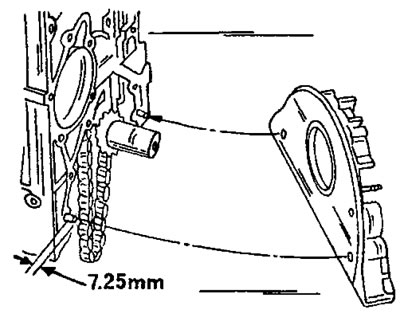
Figure 86. Installing the front bearing shield. Pay attention to the correct protrusions of the centering pins. Cover the surface indicated by the right arrow with a sealing compound.
- When installing the oil pump, place the drive chain on the oil pump sprocket, install the oil pump and insert spacer plates between the pump and the cylinder block. The installation of the oil pump is shown in Figure 87. Tighten the mounting bolts. The two left bolts are tightened to a torque of 19 Nm, and the two right bolts to a torque of 13 Nm. Since the drive chain is located at the front, you should look into the open engine crankcase.
- Install the oil pan with a new gasket.
- Install the oil pickup tube with a new gasket. Tighten three bolts to 4-5 Nm.
- Install the flywheel. Coat the threads of the new bolts with Loctite liquid locking compound. When tightening the bolts, lock the flywheel to prevent rotation and tighten the bolts to 50 Nm.
- Install the driven disc and the leading disc of the clutch and align the disc with the centering shaft. Insert the mounting bolts and tighten them evenly around the circumference with a tightening torque of 22 Nm.
- Install the junction box with a new gasket. Tighten the two bolts to a torque of 16 Nm. Install the plug with a new gasket and tighten to a torque of 20 Nm.
- Install the water pump with a new gasket (Figure 88) and tighten the five bolts to a torque of 15 Nm.
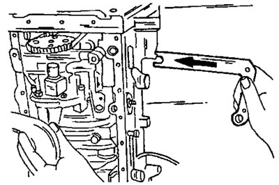
Figure 87. Installing the oil pump. Insert the spacer plates as shown.
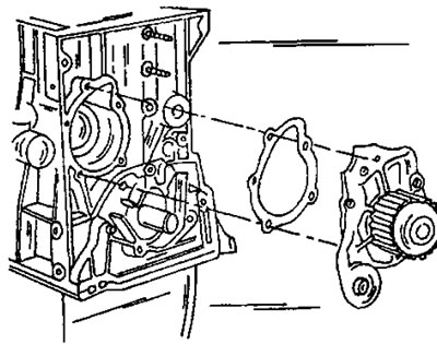
Figure 88. Installing the water pump.
- Screw on the timing belt tension roller.
- Check the fit of the two cylinder block centering bushings.
- Place the unlubricated cylinder head gasket with the marking located at the rear left facing up.
- Install the cylinder head in accordance with the relevant sections. Follow the appropriate instructions and tighten the cylinder head bolts.
- Adjust valve clearances (section 2.4.5).
- Screw two temperature switches into the thermostat housing and tighten them with a tightening torque of 18 Nm.
- Install the thermostat with two new gaskets and the fitting into the thermostat housing.
- Install the assembled thermostat housing onto the cylinder head.
- Remove the camshaft toothed pulley temporarily installed for adjusting valve clearances, press in the oil seal with a rod of the appropriate diameter and install the cover.
- Install the camshaft timing pulley. In this case, the camshaft should be held from turning in the manner described above.
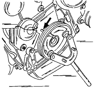
Figure 89. Holding the belt pulley while tightening the bolt. Do not use the locking pin (arrow).
- Set the crankshaft and camshaft to their original position for adjustment and install the timing belt as already described for this type of engine.
- Install the crankshaft pulley. When tightening the mounting bolt, lock the belt pulley with a bent spanner as shown in Figure 89, but under no circumstances with the locking pin indicated by the arrow.
- All other work is carried out in reverse order. The crankshaft toothed pulley bolt is tightened to a torque of 110 Nm.