



Table of contents: 2.8.1. Removing and installing the…🠇 2.8.2. Removing and installing the…🠇 2.8.3. Removing and installing the…🠇 2.8.4. Removing and installing the…🠇 2.8.5. Using a special tool for…🠇
Although all engine types use a toothed belt timing drive, different parts are used, primarily for tensioning, i.e. adjusting, the toothed belt. It is especially important to note that Peugeot service stations use a special tool to check the belt tension. Without such a tool, you need to have a certain amount of experience to replace the timing belt.
Removing and installing a timing belt when replacing it is easier, since you can remember the tension of the installed belt and, when installing a new belt, tension it in the same way as the old one. The case of a broken toothed belt should be especially highlighted. The timing belt should be replaced every 100,000 km. If the mileage exceeds this, the belt is highly likely to break. This has very bad consequences, as the valves hit the pistons. If such a case of a timing belt break occurs, in addition to removing the belt, it is necessary to remove the cylinder head to check for damage to the valves and pistons.
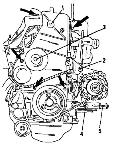
Figure 138. Location of protective covers (1) and (3) of the toothed belt. The arrows indicate the location of the bolts. Also shown: 2. Generator mounting bolt; 4. Set bolt; 5. Belt tension adjustment bolt
2.8.1. Removing and installing the timing belt (tU type engines)
- Timing belt installation on these engines is described in the engine assembly section. The following description only concerns the removal of the timing belt.
- As mentioned, proper belt tensioning after installation requires a special tool, which is recommended to be purchased before removing the belt. A qualified mechanic can measure the tension of an installed belt using a bizmen to ensure the same tension is maintained after replacing the timing belt. The use of the special tool is described in section 2.8.4 for the case where this tool is available.
- When replacing the timing belt, the right front wheel must be raised.
- Loosen the right front wheel nuts, raise the right front side of the car and place a stand under the body. Remove the wheel.
- Using Figure 138, remove both timing belt guards. The arrows indicate the location of the bolts. Release the wiring harness located on the housings.
- Engage fifth gear and turn the hub of the raised front wheel until the piston of the first cylinder is in the top dead center position of the compression stroke. In this position, insert the flywheel and toothed pulley locking rods. Figure 139 shows the position of the flywheel locking pin. Figure 140 shows the position of the toothed pulley locking pin. Figure 23 shows the appearance of the locking pins. The diameter is 8 and 10 mm.
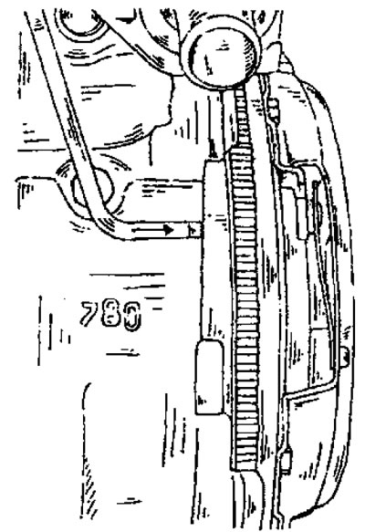
Figure 139. Locking the flywheel with a locking pin.
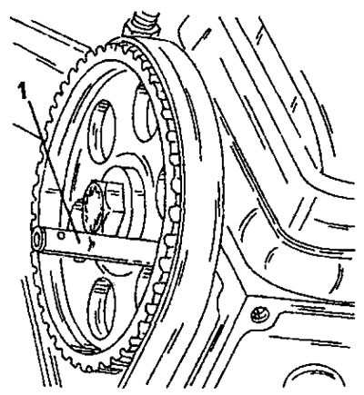
Figure 140. Locking the toothed pulley with a locking pin. The pin fits into the corresponding hole from the inside.
- Loosen the generator mount and remove the generator. Figure 138 shows the arrangement of the parts.
- Loosen the three crankshaft belt pulley mounting bolts and remove the belt pulley. If the pulley is firmly stuck, carefully place a crowbar first on the left and then on the right and press the pulley out.
- Unscrew the timing belt protective cover next to the crankshaft belt pulley.
- Loosen the timing belt tension roller nut, push the roller outward to relieve the belt, and remove the timing belt. Apply paint to the outside of the belt to indicate the direction of the belt's movement. It is best to apply an arrow indicating the direction of the belt's working movement.
- To avoid damage, do not allow the timing belt to come into contact with oils and grease. The best way to store a timing belt is to hang it on a nail on the wall, making sure it is not bent.
- The installation of the toothed belt, as already mentioned, is described when assembling the TU type engine.
2.8.2. Removing and installing the timing belt on an XU7 engine (with a working volume of 1.8 liters)
Removal and installation on this engine are carried out in the same way as on the XU10 engine, instructions for which are given in the next section.
2.8.3. Removing and installing the timing belt on an XU10 engine (8-valve engine)
- Peugeot service stations use two locking pins to hold the camshaft and crankshaft and a special indicator to check the timing belt tension. If the timing belt breaks, it is recommended to tow the vehicle to a service station. If you just need to replace or remove and install the timing belt, you should follow the following instructions step by step. First, lift the front of the car from the side of the crankshaft belt pulley and place a stand under the body. Remove the wheel and remove the shield in the inner wheel well.
- Loosen the alternator drive belt tensioner and remove the belt. Remove the remaining belts as well.
- Push aside the fuel lines located on top.
- Turn the crankshaft using the wrench head on the crankshaft belt pulley bolt until the two holes for installing the locking pins align. For the crankshaft, this position is approximately 11 o'clock, and for the camshaft, 8 o'clock.
- While holding the crankshaft from turning, engage the gear and loosen the crankshaft belt pulley bolt. Never hold the crankshaft with a locking pin. Unscrew the lower timing belt cover.
- Remove the crankshaft pulley without turning the crankshaft. You may need to use a puller to do this.
- If the vehicle is equipped with power steering and air conditioning, remove the automatic tensioner or manual drive belt adjuster and remove the belt.
- Unscrew both timing belt protective covers. Remove the washer located on the crankshaft.
- Now you can remove the timing belt. If there is no indicator for checking the timing belt tension, grasp the timing belt with your thumb and index finger and move the belt in different directions. Remember the movement of the timing belt. You can also press the belt inward and measure the belt deflection from some reference point with a measuring ruler. Record the measured value.
- Loosen the timing belt tensioner bolt (Figure 142), press the tension roller outward and remove the toothed belt. If required, the camshaft timing pulley, crankshaft timing pulley or tension roller may also be replaced. Regardless of the type of work, do not turn either the camshaft or the crankshaft under any circumstances.
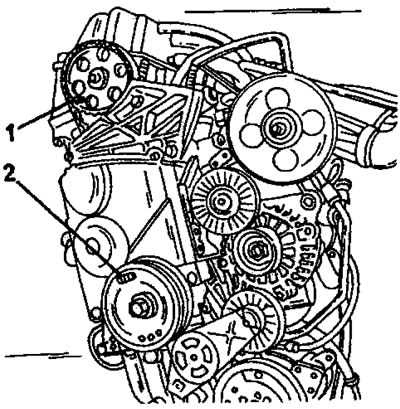
Figure 141. Insert two locking pins in the indicated locations. Into the toothed pulley of the camshaft in place (1), into the belt pulley of the crankshaft from side (2).
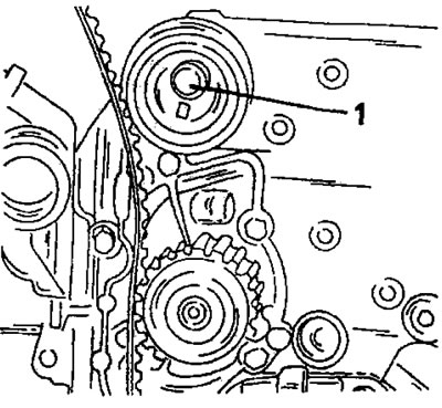
Figure 142. Pull the tension roller outward after loosening the bolt (1). This will loosen the belt and allow it to be removed.
- Place a new timing belt on both timing pulleys, the water pump pulley and route the belt behind the tension roller. The long side of the belt must be applied with tension. Do not allow the toothed pulleys to turn unless the locking pins are installed. If the pins are installed, remove them.
- Place the belt pulley and washer onto the crankshaft and secure with a bolt.
- Loosen the tension roller and allow it to rest against the timing belt, temporarily tighten the bolt.
- Turn the crankshaft at least 2 revolutions (with the head of a wrench on the belt pulley bolt), to ensure the toothed belt fits properly. Turn the shaft clockwise, looking from the front. After turning the shaft, set it to the top dead center position of the compression stroke of the first cylinder, that is, the "0" mark on the flywheel should be opposite the "0" mark on the ignition timing adjustment scale.
- Loosen the tension roller bolt, wait until the roller is pressed against the belt, and tighten the bolt to a torque of 20 Nm.
- Check that the belt tension is the same as it was before removing the belt. Adjustment can be made by deflecting the tension roller. There are two holes on the roller, through which the roller can be moved using a trunnion key.
Please note: The above instructions are given in good faith but without guarantee. The work can only be performed professionally using special tools.
- Remove the crankshaft pulley again, install the timing belt guards and put the belt pulley back on. While holding the crankshaft from turning, tighten the bolt to a torque of 110 Nm.
- Install all remaining parts.
2.8.4. Removing and installing the timing belt (16-valve engines type XU10)
As can be seen from Figure 144, these engines have two camshafts. The water pump is also driven via a timing belt. The timing belt must be replaced after 100,000 km.
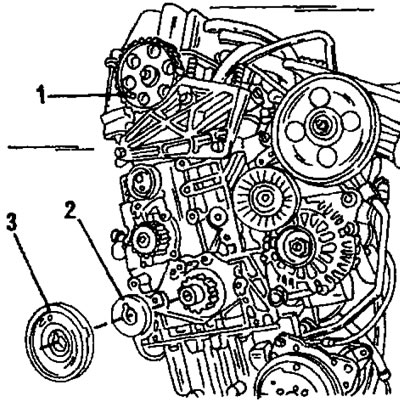
Figure 143. XU type engine with the timing belt removed. The cutout of the washer (2) is placed on the key. 1. Locking pin; 2. Washer; 3. Crankshaft belt pulley
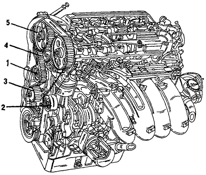
Figure 144. Timing drive of a 16-valve engine.
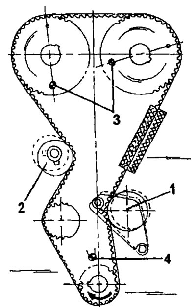
Figure 145. Installing the timing belt on a 16-valve engine. 1. Belt tension roller; 2. Belt tension roller; 3. Locking pins of camshaft toothed pulleys; 4. Crankshaft locking pin
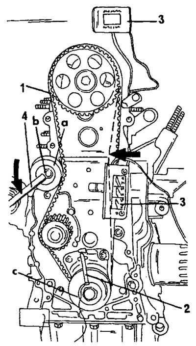
Figure 146. Installing and tensioning the toothed belt on an XU10 engine using a special tool. The letters represent the three main working operations. and the movement of the tension roller; b tightening the nut; with crankshaft rotation (2 full turns); 1. Camshaft locking pin; 2. Crankshaft locking pin; 3. Timing belt tension indicator; 4. Trunnion key
- As with the 8-valve engine, special tools are also required here and the work described below should only be performed for a simple belt replacement.
- Before unscrewing the toothed belt protective covers, the work is carried out in the same way as on 8-valve engines. Toothed pulleys and toothed belt are shown in Figure 145.
- Due to the presence of two camshafts and the associated differences in drives, removal and installation of the timing drive is significantly more complex than on an engine with a single camshaft, since the work is performed with two tensioners.
- Turn the crankshaft using the wrench head on the crankshaft belt pulley bolt until the two holes for installing the locking pins align. Figure 145 shows the installation locations of the locking pins.
- While holding the crankshaft from turning, engage the gear and loosen the crankshaft belt pulley bolt. Never hold the crankshaft with a locking pin. Unscrew the lower timing belt cover.
- Insert a 10mm locking pin and remove the crankshaft pulley without turning the crankshaft.
- If the vehicle is equipped with power steering and air conditioning, remove the automatic tensioner or manual drive belt adjuster and remove the belt.
- Now you can remove the timing belt. If there is no indicator for checking the timing belt tension, grasp the timing belt with your thumb and index finger and move the belt in different directions. Remember the movement of the timing belt. You can also press the belt inward and measure the belt deflection from some reference point with a measuring ruler. Measurements should be taken on both sides of the timing belt. Record the measured value.
- Loosen the bolts of both timing belt tensioners. The roller (2) is fastened in the same way as shown in Figure 142, and the roller (1) is fastened with two bolts, one of which is screwed into the slot. Press the tension rollers outward and remove the timing belt. If required, the camshaft timing pulleys, crankshaft timing pulley or tension rollers can also be replaced. Regardless of the type of work, do not under any circumstances turn either the camshafts or the crankshaft.
- Install a new timing belt. It has colored markings (two for the crankshaft and one for the camshafts). Place the timing belt on the timing pulleys in accordance with the timing belt.
- Loosen both tension rollers and press the left tension roller against the timing belt so that the timing belt is tensioned, i.e. the previous belt tension should be restored. Tighten this roller fastening to a torque of 20 Nm.
- Turn the tension roller (1) towards the timing belt (clockwise) when restoring the previous timing belt tension, tighten the bolt to a torque of 20 Nm. Two holes on the roller are used to reposition it, using a camshaft key.
- Rotate the crankshaft 2 revolutions to a position where the locking pins of both camshaft timing pulleys and the crankshaft timing belt pulley can be reinserted. Check the timing belt tension again. It should be the same on both sides as it was measured before removing the belt. Otherwise, repeat all the work from the beginning.
Please note: The above instructions are given in good faith but without guarantee. The work can only be performed professionally using special tools.
2.8.5. Using a special tool for adjusting the gas distribution mechanism drive
In many cases, it is necessary to rent or purchase a special tool. For this reason, a brief description of the operating procedures for both types of engines under consideration is provided.
8-valve XU type engine
- The work is carried out using Figure 146 in the following sequence:
- Insert both locking pins (1) and (2).
- Remove the locking pin from the camshaft timing pulley.
- Place the 4099-T (3) timing belt tension indicator on the timing belt as shown.
- Insert the trunnion key (4) to turn the tension roller.
- Press the toothed belt in the direction of the large arrow until the dashed line is positioned.
- Turn the tension roller (a) with a pin wrench in the direction of the arrow (to the left) until the instrument reading is 30+/2.
- Tighten nut (b) to 20 Nm.
- Pull both locking pins (2) out of the crankshaft and remove the tool and the trunnion key.
- Turn the crankshaft two full revolutions (four engine revolutions).
- Reinsert the locking pin (2) into the crankshaft and replace the measuring instrument (3).
- Check that the instrument reading is 44 +/- 2. If not, repeat the entire operation from the beginning.
16-valve engine type XU10
- Insert the locking pins into the camshaft timing pulleys and into the crankshaft in accordance with Fig. 145.
- Install the timing belt following the instructions above.
- Bring the tension rollers into contact with the timing belt.
- Place the measuring device shown in Figure 146 on the long section of belt shown in the figure.
- Press the roller against the belt so that the instrument reading is 45.
- Loosen the roller again and press it against the belt until the instrument reading is 22±2. Tighten the tension roller bolts (1) to a torque of 20 Nm.
- Move the tension roller (2) towards the belt so that the instrument reading is 32±2 and tighten the bolt to a torque of 20 Nm.
- Pull both locking pins (2) out of the crankshaft and remove the tool and turn the crankshaft two full revolutions (four engine revolutions) and insert the crankshaft locking pin. If the hole is clear, turn the engine two more revolutions.
- Replace the measuring device and check that the reading is 53±2. If not, repeat the entire procedure from the beginning.
TU type engines
- After installing the timing belt, check that it is tensioned on its long section and turn the tension roller to the left to tighten the belt slightly. The condition is that the tension roller rotates easily without jamming.
- Tighten the nut (1) in Fig. 147 and pull out both locking pins.
- Place the measuring device (2) shown in Figure 147 on the toothed belt and loosen the nut (1) again.
- Turn the tension roller to the left until the measuring instrument shows 45.
- Tighten the nut again and remove the device.
- Turn the crankshaft four revolutions and wait until the timing belt settles.
- Reinstall the measuring instrument and loosen the nut (1).
- Turn the tension roller to the left until the measuring instrument shows 40 (with a new belt) or 36 (with a used belt). A belt that has been in use for one hour is already considered used. Tighten the nut (1) again.
- If the instrument readings are higher, repeat the work from the beginning.
- Remove the measuring instrument and turn the crankshaft two revolutions. Insert the locking pin into the flywheel (see Figure 139). This shouldn't be difficult.
- Reinstall the measuring instrument in accordance with Figure 147 and read the readings again. The instrument reading should be 51±3 for a new belt and 45±3 for a used toothed belt.
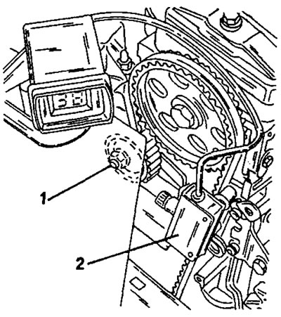
Figure 147. Using a timing belt tension gauge on a TU type engine. 1. Tension roller nut; 2. Measuring instrument