



Table of contents: 2.7.1. Measuring the axial play of…🠇 2.7.2. Checking the details 🠇 2.7.3. Installing the crankshaft 🠇 2.7.4 Replacing the rear crankshaft…🠇 2.7.5. Replacing the front…🠇 2.7.6. Flywheel 🠇
Removing the crankshaft has already been described in the section on engine disassembly. The crankshaft runs in five bearings. The main bearing journals and connecting rod bearing journals can be turned once, that is, there are bearing shells of the same increased size.
The axial play of the crankshaft is adjusted by the spacer washers at the second crankshaft bearing.
The crankshaft is sealed at the front and rear by means of an oil seal.
2.7.1. Measuring the axial play of the crankshaft
Before removing the crankshaft, the amount of its axial play should be determined in order to prepare oversized expansion washers for installation, if necessary. Carry out the following work:
- Install a dial indicator on the front side of the cylinder block, as shown in Figure 77, and press the crankshaft along the axis in one direction with a screwdriver. Reset the dial indicator scale to zero.
- Press on the crankshaft with a screwdriver from the other side and read the reading from the dial indicator scale. The value must be within the tolerance range. Record the measurement result. If it exceeds the wear limit, oversized spacer washers must be installed during assembly (sometimes only the expansion washers wear out).
- Remove the dial indicator.
- Remove the crankshaft according to the instructions section 2.2. for the corresponding engine type.
2.7.2. Checking the details
- Clean the crankshaft thoroughly. Pay special attention to the cleanliness of the lubrication holes.
- Carefully check the crankshaft for damage and take precise measurements of the main and connecting rod journals with a micrometer. In this case, proceed in accordance with Figure 134. The right side of the figure shows the directions of measurements for each neck, that is, six measurements must be taken on each neck. The difference between the measurement in the direction towards the crankshaft web and the measurement in the direction perpendicular to the crankshaft web determines its out-of-roundness; the difference between the measurement at one end and the other end of the crankshaft determines its taper. Both differences should not exceed 0.007 mm. The crankshaft main bearing journals and crankpin journals may be reground once to allow the crankshaft to be installed with oversized bearing shells.
- Clamp the crankshaft in the centers of a lathe or place the outer journals of the shaft in prisms, as shown in Figure 135, and check the shaft runout by installing the measuring probe of the dial indicator on the middle journal. The runout should not exceed 0.02 mm. Otherwise, the crankshaft must be replaced.
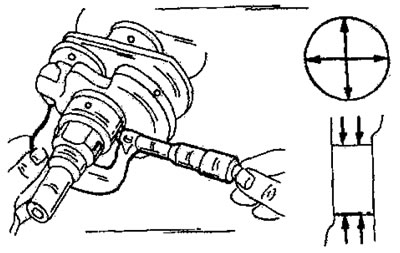
Figure 134. Measuring the crankshaft main journals. The directions of measurements are shown on the right side of the figure.
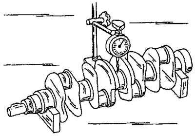
Figure 135. Measuring crankshaft runout (the outer support necks are embedded in the prisms).
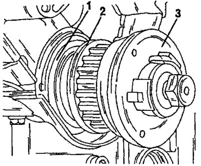
Figure 136. Removing the front crankshaft oil seal. 1. Seal; 2. Pressure washer; 3. Crankshaft toothed pulley
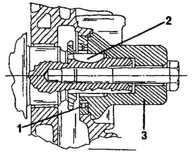
Figure 137.
2.7.3. Installing the crankshaft
The description of the crankshaft installation is given in connection with the installation of the engine in section 2.3. for the corresponding engine type. It is important to install the liners correctly, as there are differences between individual engine types. The liners with lubrication grooves must be installed in the required locations. It is necessary to install both expansion washers of the same thickness.
2.7.4 Replacing the rear crankshaft oil seal
- A description is given that is common to all types of engines.
- The oil seal can be replaced with the flywheel removed. This may be necessary when the clutch starts to slip due to contamination with oil leaking from the engine crankcase.
- Remove the oil seal using a screwdriver without damaging the engine crankcase and crankshaft flange. To make it easier to remove the oil seal, you can screw two self-tapping screws into the outside of the oil seal and alternately press a screwdriver against the screw heads. Step by step the seal comes out.
- Check the working surface on the crankshaft. If there is wear on the surface from the old seal, the new seal can be pressed into the engine crankcase a little deeper.
- Carefully press in the new seal using a punch of the appropriate diameter. Lubricate the outside of the oil seal with engine oil and its sealing lips with universal grease. If the surface of the crankshaft is not worn, the oil seal is pressed in flush, otherwise the outer surface of the oil seal should be slightly recessed. Check that the seal is pressed evenly around the circumference.
2.7.5. Replacing the front crankshaft oil seal
The front oil seal is located behind the crankshaft sprocket in the engine crankcase cover or in the front cover (xU type engines) and can be replaced without removing the engine, but the timing belt must be removed. Removing the oil seal is not easy, as it is located in a recess in the engine crankcase. To remove the oil seal, you can try to screw two self-tapping screws into the oil seal and then pull the oil seal out with a screwdriver, as described for the rear oil seal. On the XU10 engine, special attention should be paid to the installation position of the oil seal, which was described during engine assembly (see also Figure 79).
In general, when replacing the oil seal, the following work is performed:
- Loosen and remove the alternator drive belt.
- Unscrew the crankshaft belt pulley from the flange.
- Loosen the bolt securing the toothed pulley or belt pulley of the crankshaft. To prevent the crankshaft from turning, engage the gear (with the engine installed on the vehicle) or insert a screwdriver into the flywheel ring teeth (with the engine removed).
- Remove the timing belt.
- On a TU engine, remove the crankshaft toothed pulley using Figure 136. To press the toothed pulley out, you can place two screwdrivers under the toothed pulley flange. Remove the pressure washer (2) from the crankshaft and then remove the released oil seal. On other types of engines, the work is performed in a similar manner.
- Lubricate the sealing lips and the contact surface with the pressure washer of the new oil seal with engine oil. When the engine is installed on a vehicle, the oil seal is usually pressed into the desired position using a special tool. The device has the shape shown in Figure 137, and the toothed pulley mounting bolt is used to press the seal into the desired position. Such a device can be made independently from a piece of pipe with a washer that covers the open side of the pipe. Before installation, check whether the key is installed on the crankshaft.
- If the engine is removed, carefully press the oil seal into position using a piece of pipe, being careful not to damage it.
- Place the pressure washer and crankshaft pulley on, making sure that the key does not move.
- Tighten the crankshaft timing belt or toothed pulley bolt to the specified torque. In this case, the crankshaft must be locked in an appropriate manner (engage gear or lock the flywheel).
- Install the timing drive following the instructions section 2.3. for engine assembly.
Original can be viewed at [Peugeotbook.ru]
2.7.6. Flywheel
- If the flywheel ring gear is damaged, it is also necessary to check the starter pinion, as both parts wear out together.
- The flywheel bolts are either offset or have a centering pin so that the flywheel can only be installed in one position. When installing the flywheel, cover the bolt threads with "Loctite" contouring agent (except for the bolts on the XU type engine). Tighten the bolts evenly and crosswise to the specified torque (not the same torque for all engine types).