



Table of contents: 2.2.1 Removing the cylinder head 🠇 2.2.2 Complete disassembly of the…🠇
Before starting work, thoroughly clean all external surfaces of the engine. First, cover all openings with clean rags to prevent foreign objects from getting inside the engine.
Engine disassembly is described in detail below in the section titled "Repair and Overhaul." This section describes tasks that can be performed both with the engine removed and while it's still in the vehicle, eliminating the need to repeat descriptions of specific tasks associated with engine disassembly. If complete disassembly of the engine is required. you just need to combine individual work operations, and in the specified sequence. For greater clarity, both groups of gasoline engines are described separately. Description of diesel engines is given in a special section.
In general, it is important to always remember to mark all moving parts before removal so that they can be reinstalled in the same position if they are to be reinstalled. This applies to all engines and is especially important for pistons, valves, bearing caps and bearing shells. Place the removed parts so as not to mix them up.
Under no circumstances should bearing and mating surfaces be marked with a drafting tool or even stamped with numbers on them. Paint is best for marking. The valves are best installed in the holes in the bottom of an inverted cardboard box, so that their numbers can be written next to them on the box. Figure 21 shows the location of the removed valves of an 8-valve engine.
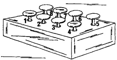
Figure 21. The valves can be installed into the holes in the bottom of the inverted cardboard box in the order in which they will be installed.
Most parts are made of aluminum and require handling accordingly. If hammer blows are required to separate individual parts, only a rubber, plastic or leather hammer should be used.
If a prescribed mounting stand is not available, it is best to cut wooden blocks to size to allow the engine to be mounted on them with access to the top and bottom of the engine. After removal, the cylinder head can be secured in a vice using a metal bracket screwed to the intake manifold studs.
The following text first describes how to remove the cylinder head, as this job will need to be performed at least once during the life of the vehicle. In this case, the description is given separately for engine groups.
2.2.1 Removing the cylinder head
XU engine
To remove and install the cylinder head, a special tool must be available to lock the camshaft toothed pulley and then lock the flywheel to avoid misalignment of the required positions of the crankshaft and camshaft. These devices can be made independently.
- Disconnect the wires from the battery. Move the wires away from the battery so that they do not come back and cause a short circuit.
- Drain the coolant from the cooling system. If the liquid is not old, drain it into a clean container.
- Remove the air filter, air intake hose, etc.
- Disconnect the throttle cable, fuel lines, hoses connected to the cylinder head, fuel injection system connections, upper oil dipstick tube mount and front muffler pipe in the specified order. Disconnect the pipe from the mount on the gearbox and lower it down.
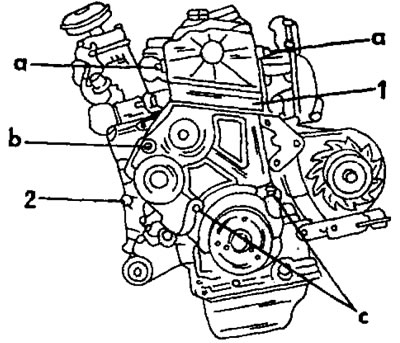
Fig. 22. Removing and installing the two timing covers on the front of a TU engine. References to letter and number designations are provided in the text.
- Disconnect the ignition module wiring harnesses from the ignition coil and temperature switch. Release the top dead center sensor connection from the mounting bracket.
- Using Figure 22, remove both timing cover assemblies. The bolts are located, looking from the front of the engine, in the following locations:; one bolt on the left and one on the right (a), one bolt on the left side approximately in the middle (b), and two bolts on the bottom side directly above the crankshaft pulley (c). After this, both halves of the timing cover (1) and (2) can be removed.
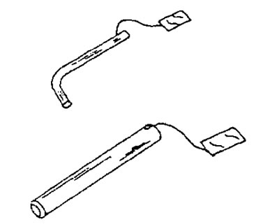
Figure 21. Locking pins for adjusting the valve timing mechanism. The flywheel locking pin is shown above; from below - to lock the camshaft toothed pulley.
- Turn the engine until the piston of the first cylinder is in the top dead center position of the compression stroke and insert the special locking pin from the rear side of the cylinder block into the flywheel. The tool shown in Figure 23 has a diameter of 6 mm. You can make such a pin yourself using the drawing.
- After locking the flywheel in the manner described, insert the locking pin into the camshaft sprocket as shown in Figure 24. This is a straight pin, shown at the bottom of Figure 23. This rod can also be made of steel or iron.
- Loosen the tension roller nut ("2" in Figure 24), move the tension roller outward and remove the drive belt. It is recommended to place an arrow on the belt indicating the direction of belt movement.
- Unscrew the two nuts securing the cylinder head cover and remove the cover. This opens the oil deflector shield, which also needs to be removed. First, remove the two spacer bushings from the studs on the left and right sides of the oil deflector shield. Figure 25 shows the parts after removing the cylinder head cover.
- In several passes, in the reverse order to that shown in Figure 26, unscrew the cylinder head bolts and remove the crankshaft from the cylinder head as a single unit. After this, you can remove the cylinder head. At Peugeot service stations, two bent levers are used for this purpose, inserted into two holes for the cylinder head bolts. You can make such levers yourself and use them to remove the cylinder head from the cylinder block, as shown in Figure 27. To release the gasket, rock the head in both directions. If the cylinder head is removed without levers, you can grab the intake and exhaust manifolds and rock the head in both directions until it is released. Do not remove the cylinder head immediately, as this may cause the cylinder liners to remain stuck to the head.
- Remove the cylinder head gasket and clamp the working cylinder liners with special clamps. For this purpose, two tension strips, shown in Figure 28, are suitable.
- Immediately thoroughly clean the surfaces of the cylinder head and cylinder block and carefully scrape off the remains of the cylinder head gasket with a scraper, without damaging the contact surfaces
- surfaces. Under no circumstances should you use sandpaper for this purpose.
- Cylinder head installation is described in the engine assembly section. All disconnected elements are connected in reverse order.
XU engine (with a working volume of 1.8/2.0 liters)
- Removal and installation the cylinder head of these engines is not associated with any difficulties, but a special measuring device is required to ensure the prescribed tension of the timing belt. If there is no such device, the tension of the timing belt should be checked before removing it. By pressing hard on the belt, you can measure the belt deflection with a measuring ruler. When installing the belt, it should be tensioned so that the measured deflection is ensured.
- To lock the crankshaft and camshaft, or both camshafts on a 16-valve engine, locking pins are required. These pins are inserted into the camshaft(s) and crankshaft at a certain engine position to prevent the engine from turning. The locking pins are similar to those shown in Figure 23. A rod with a diameter of 8 or 10 mm can also be used for locking. Furthermore, the diameter is not the same for both engine types. It is important to determine the required diameter. To work in the wheel well, it is necessary to raise the right side of the vehicle. Due to the differences between 8- and 16-valve engines, it is impossible to go into all the details. The following instructions are general and are followed as follows.
- Remove the right front wheel and mudguard.
- Remove the spark plugs to make it easier to turn the engine.
- Disconnect all wires connecting the cylinder head to the body and the cylinder head to the cylinder block. The same applies to hoses.
- Remove the parts shown in Figure 29. These are the hose (1), two bolts (2) and two strips (3). Then remove the air filter cover and take out the filter element.
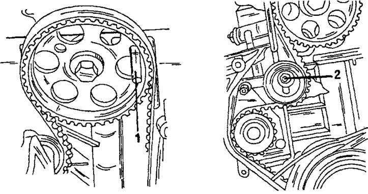
Figure 24. Locking the camshaft toothed pulley with the locking pin (1) on the left side and the belt tension roller nut (2) on the right side
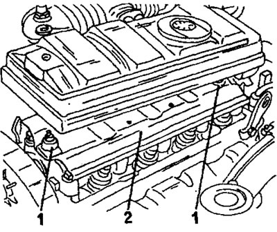
Figure 25. After removing the cylinder head cover, the following parts are exposed. 1. Expansion sleeve; 2. Oil deflector shield
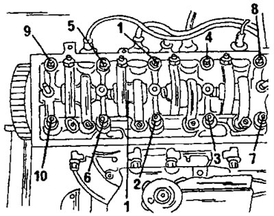
Figure 26. Cylinder head bolt tightening sequence. Loosen the bolts in reverse order.
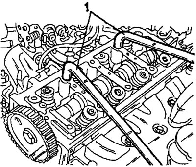
Figure 27. Lifting the cylinder head using two levers (1).
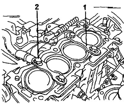
Figure 28. The cylinder liners can be secured in the cylinder block (2) with two clamping strips (1).
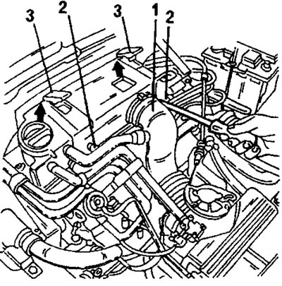
Figure 29. When removing the cylinder head of an XU engine, first remove the parts shown to gain access to the air filter on the cylinder head cover. 1. Air intake hose; 2. Right and left mounting bolts; 3. Spring bars
- Unscrew the muffler pipe from the exhaust manifold.
- The cylinder head cover and air filter are a single unit and the bolts must be unscrewed in the sequence shown in Figure 30. After this, remove the complete unit.
- Unscrew the bolt (3) and nut in Figure 11. It secures the reaction support.
- Loosen the upper right engine mount nut and support the engine with a small crane, pulley block, or other lifting device. Remove the two bolts shown in Figure 31 and lower the engine back onto the rubber mount.
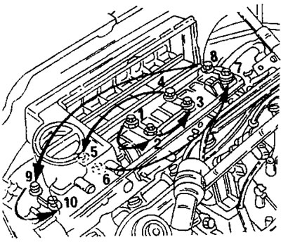
Figure 30. Loosen the ten cylinder head cover mounting bolts (and air filter) in the specified sequence.
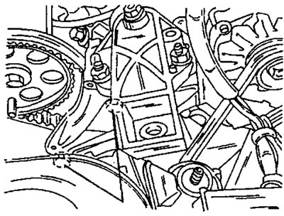
Figure 31. Remove only the two indicated engine mount bolts.
- Unscrew and remove the intake manifold.
- Remove the alternator drive belt. On some models, the power steering pump drive belt also needs to be removed.
- On an 8-valve engine, turn the crankshaft until the camshaft is set to the position shown in Figure 32. In this position, insert the locking pin (10 mm) into the camshaft toothed pulley. The pin passes through the pulley and is inserted into the hole. The crankshaft belt pulley also has a hole. Another locking pin is inserted into it to lock the crankshaft. The locking pins for the crankshaft and camshaft are different. The locking pins used at Citroën service stations are also suitable. They are numbered 7004 TG or 7014 TG for the camshaft and 7014 TN for the crankshaft. When using other pins, do not insert an 8mm pin into a 10mm hole.
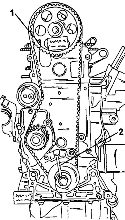
Figure 32. Front view of 8-valve engine. 1. The camshaft locking pin is inserted here; 2. The crankshaft locking pin is inserted here.
On a 16-valve engine, the work is performed in a similar manner, but the engine is turned to a position in which the toothed pulleys of both camshafts and the crankshaft belt pulley are set to the position shown in Figure 33. In this position, insert the locking pins (3) and (4) into the toothed pulleys of the camshafts and into the crankshaft belt pulley. Special locking pins are shown in the figure.
- After this, remove the timing belt, following the instructions in the relevant sections.
Subsequent work on removing the cylinder head is carried out in accordance with the instructions given in the section on engine disassembly.
On an engine with wet cylinder liners, secure all four liners with clamping strips as shown in Figure 28 to prevent the liners from coming out.
The cylinder head is installed in reverse order. The following is a description of cylinder head bolt tightening only. To tighten, you need a Torx 55 key insert, a corresponding head, and a protractor. When tightening bolts, be sure to refer to the instructions for the corresponding engine type.
8-valve engine with a displacement of 2.0 liters
- Measure the length of the cylinder head bolts from the bottom of the bolt head to the thread runout. Bolts longer than 122 mm must be replaced.
- Place a new cylinder head gasket on the cylinder block. The gasket type must match the engine number. The gasket is applied without lubrication. Check the presence of both centering bushings in the corners of the cylinder head. The protrusion on the cylinder gasket should be located on the flywheel side.
- Lubricate the threads and underside of the bolt heads with engine oil and place a washer on each bolt.
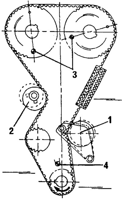
Figure 33. Timing drive of a 16-valve engine. 1. Belt tension roller; 2. Belt tension roller; 3. Camshaft locking rods; 4. Crankshaft locking rod
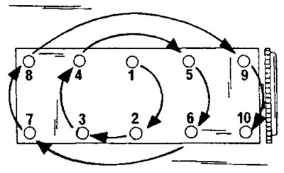
Figure 34. Cylinder head bolt tightening sequence on an 8-valve engine.
- Install the cylinder head. The camshaft timing pulley remains locked. Otherwise, it should be pre-locked with a pin. Insert a 10mm diameter pin. Tighten the cylinder head bolts by hand from the inside out.
- Tighten the bolts in the sequence shown in Figure 34 to a tightening torque of 35 Nm. To avoid damaging the bolts, use only a Torx 55 wrench.
- Tighten the bolts in the sequence shown in Figure 34 to a tightening torque of 70 Nm.
- Then, tighten the cylinder head bolts to an angle of approximately 160°, following the sequence shown in Figure 34. With a protractor, as shown in Figure 35, tightening the bolts to a specific angle is simple: after installing the wrench, turn it until the wire pointer lines up with the 165° mark. Without this measuring device, assume that 180° is half a turn. You can also draw a 90° angle and divide it into six equal hours. One sector is 15°, which should be subtracted from half a turn. This method may be complicated, but it is the only one that can be offered in the absence of a protractor.
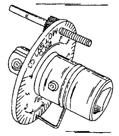
Figure 35. To tighten the bolts to a certain angle, a protractor of the specified type is used.
- Tightening the cylinder head bolts when the engine is warm or after a certain mileage is not required.
- Install the timing belt and all removed parts.
16-valve engine
- To tighten the cylinder head bolts, use only a Torx 55 wrench. Do not use auxiliary tools.
- Place an unlubricated cylinder head gasket on the cylinder block.
- Measure the length of the cylinder head bolts from the bottom of the bolt head to the thread runout. Bolts longer than 110 mm must be replaced.
- Lubricate the threads and underside of the bolt heads with engine oil and place a washer on each bolt.
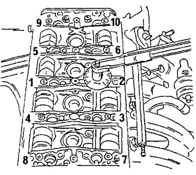
Figure 36. Cylinder head bolt tightening sequence on an 8-valve engine. The key has a protractor attached to it for tightening the bolts to a certain angle.
- Tighten the bolts in the sequence shown in Figure 36 to a tightening torque of 40 Nm.
- Tighten the bolts in the sequence shown in Figure 36 to a tightening torque of 75 Nm.
- After this, in the sequence shown in Figure 34, tighten the cylinder head bolts to an angle of approximately 165° using the method indicated above.
- Tightening the cylinder head bolts when the engine is warm or after a certain mileage is not required.
- Install the timing belt and all removed parts.
XU7 engine (with a working volume of 1.8 liters)
- Remove the cylinder liners clamping strips.
- Clean the contact surfaces of the cylinder block and engine block with a cleaning agent. Never use a hard scraper or sandpaper for cleaning.
- If necessary, measure the protrusions of the cylinder liners, following the instructions in the relevant section.
- The cylinder head is installed as follows:
Place a new cylinder head gasket on the cylinder block. The gasket type must match the engine number. Gaskets are available in normal and extra large sizes. The gasket is applied without lubrication.
Lubricate the threads and underside of the bolt heads with engine oil and place a washer on each bolt.
Install the cylinder head and insert the 10 bolts. Tighten the bolts by hand from the inside out.
Tighten the bolts in the sequence shown in Figure 37 to a torque of 45 Nm. To avoid damaging the bolts, use only a Torx 55 wrench. Figure 38 shows the bolt head.
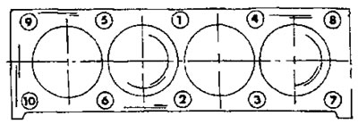
Figure 37. Cylinder head bolt tightening sequence on the XU7 engine (with a working volume of 1.8 liters).
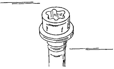
Figure 38. Shape of the head of the "Torx" cylinder head bolt. To tighten bolts, use only appropriately shaped wrench inserts.
- Tighten the bolts in the sequence shown in Figure 37 to a tightening torque of 60 Nm.
- Loosen all bolts again.
- Tighten the bolts in the sequence shown in Figure 37 to a tightening torque of 20 Nm.
- Tighten the bolts in the sequence shown in Figure 37 to an angle of approximately 300°. With a protractor, as shown in Figure 35, tightening the bolts to a specific angle is simple: after installing the wrench, turn it until the wire pointer lines up with the 300° mark. Without this measuring device, assume that 270° is three-quarters of a turn. You can draw a 90° angle and divide it into six equal hours. The two sectors make up an angle of 30°, which should be added to three quarters of a turn. This method may be complicated, but it is the only one that can be offered in the absence of a protractor.
- Tightening the cylinder head bolts when the engine is warm or after a certain mileage is not required.
- Install the timing belt and all removed parts.
2.2.2 Complete disassembly of the engine
After removing the engine from the vehicle and the timing belt from the engine, complete disassembly of the engine is performed in the sequence below for each engine type.
TU type engines (with a working volume of 1.4/1.6 liters)
Remove the oil filter from the engine. This requires a special key. The filter is visible in Figure 39. On the same side of the engine, unscrew the two electrical sensors.
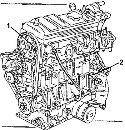
Figure 39. Installing pins to lock the position of the timing mechanism. 1. Locking the camshaft toothed pulley; 2. Flywheel lock
Loosen the two bolts (1) on the left side of the cooling system outlet (3) (Figure 40) and two bolts on the right side of the case. Remove the water pump from the cylinder block.
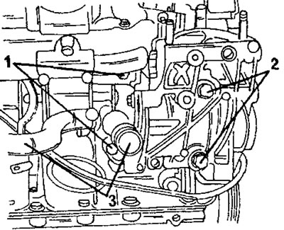
Figure 40. Removing the water pump. The pump is secured with bolts (1) and (2). The water hose is connected to the pump nipple (3).
- While holding the flywheel from turning, unscrew the crankshaft toothed pulley bolt and the belt pulley housing projection. There is a metal plate behind the toothed pulley that needs to be removed.
- Remove the ignition distributor together with the ignition wires, in accordance with the instructions in the section "Ignition system".
- Loosen the clutch mounting bolts evenly and crosswise. At the same time, you should hold the flywheel from turning. The best way to do this is to insert a powerful screwdriver between the teeth of the flywheel ring gear. In this case, one of the cylinder block flange bolts can be used as a stop for a screwdriver. Before removing the clutch, make a mark with a punch on the flywheel and clutch basket to ensure that the clutch is installed in its original position (unless the clutch and/or flywheel are being replaced).
- Loosen the flywheel mounting bolts one by one. There is no need to mark the flywheel installation position, since the flywheel can only be installed in one position. When unscrewing the bolts, the flywheel should be held from turning in the manner described above. A firmly stuck flywheel can be knocked out with a rubber hammer. Make sure the flywheel does not fall.
- Using a suitable spanner, remove the plug from the front of the engine directly above the crankshaft flange. Also unscrew the bolt located above the plug. The location of these parts is shown in Figure 41.
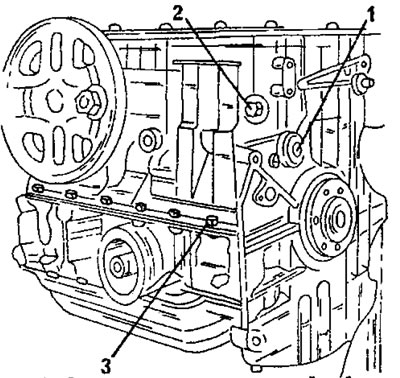
Figure 41. Location of some parts on the cylinder block. 1. Hexagon socket plug; 2. Bolt; 3. Bolts (16 pieces) of the lower part of the crankcase
- Turn the cylinder block over and unscrew the 16 bolts of the lower half of the engine crankcase from the cylinder block. These bolts are designated (3) in Figure 41. Loosen the 19 oil pan bolts and remove the oil pan. Carefully tap the stuck crankcase.
- Unscrew the three oil pump bolts and remove the pump. At the same time, disengage the pump sprocket from the drive chain. Remove the sprocket from the crankshaft and remove the chain. Use side cutters to remove the key from the crankshaft. This work operation is shown in Figure 42.
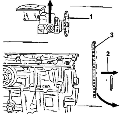
Figure 42. Removing the oil pump and drive chain on a TU type engine. 1. Oil pump; 2. Asterisk; 3. Drive chain
- Loosen and remove 10 main bearing bolts evenly and crosswise. These bolts secure the lower half of the engine crankcase to the cylinder block and also the crankshaft. Remove the lower half of the engine crankcase. If necessary, use a rubber mallet. Pull out the oil seal (radial seal) crankshaft.
- Mark the four connecting rod bearing caps with a punch (connecting rod bearing No. 1 - one punch strike, connecting rod bearing No. 2 - two punch strikes, etc.) and unscrew the connecting rod bearing nuts. When removing the covers, turn the crankshaft accordingly so that two connecting rod bearings are located on the upper side. Remove the covers one by one and immediately connect the bearing shells to the covers.
- Pull out the crankshaft and remove the main bearing shells from the main bores.
- Mark the liners according to their installation position. The same applies to the liners in the lower part of the engine crankcase. The liners must be in a set of one bearing. Remove both spacer washers from the second main bearing (counting from the flywheel side).
- Unscrew the clamping bars of the working cylinder liners and pull out the liners with the pistons and connecting rods inside them. Mark the cylinder numbers on the working liners if they are to be re-installed. If the working sleeve is jammed in the hole, turn the cylinder block on its side and knock it out from the bottom with a hard wooden rod.
- Disassemble the pistons and connecting rods following the instructions in section 2.5.
- If necessary, disassemble the cylinder head following the instructions in section 2.4 for this engine type.
XU10 engines
- The following description assumes that the engine is fully assembled. Consider the differences between an 8-valve and a 16-valve engine. The basis of the description is an 8-valve engine.
- Drain the oil from the engine.
- Remove all parts installed on the cylinder head.
- Lock the flywheel appropriately. To do this, place a blocker on the engine, as shown in Figure 43, or insert a powerful screwdriver into the flywheel teeth. Unscrew the bolt from the inside of the crankshaft belt pulley from the front of the engine, remove the bolt with the washer and remove the belt pulley from the shaft (if necessary, use a crowbar).
- Loosen the bolts indicated by arrows in Figure 44 and remove both halves of the timing belt protective cover.
- Remove the oil dipstick tube from the engine (unscrew the bolt from above) and pull it out of the cylinder block.
- Unscrew the oil filter using a special wrench. If you don't have such a key, pierce the filter with a powerful screwdriver and unscrew the filter, using the screwdriver as a lever. The filter is still replaced and it doesn't matter if it gets damaged during removal.
- While the flywheel is still locked, loosen the clutch mounting bolts crosswise. Before removing the clutch, make a mark with a punch on the flywheel and clutch basket to ensure that the clutch is installed in its original position (unless the clutch and/or flywheel are being replaced). Remove the clutch and take out the driven disk from the flywheel.
- On an 8-valve engine, while holding the camshaft properly from turning, loosen and remove the bolt in the middle. The method for holding the camshaft is shown in Figure 45. On a 16-valve engine, unscrew the bolts of both camshafts using the method described above. The relative position of the crankshaft and camshaft(s) is not important, since during engine assembly the timing drive adjustment is still performed again.
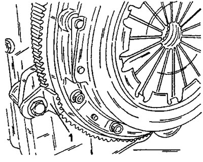
Figure 43. The flywheel can be held from turning using a toothed segment (1). It is suitable for all engines.
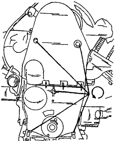
Figure 44. The arrows indicate the location of the bolts securing the timing belt protective cover.
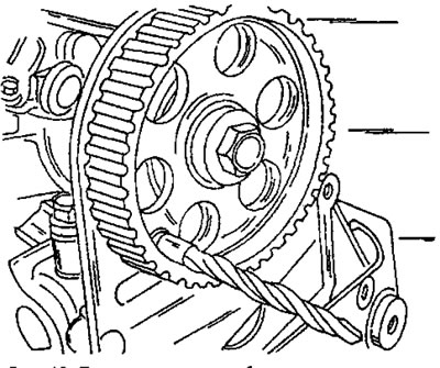
Figure 45. When loosening the camshaft pulley bolt, insert the drill in the manner shown.
- Remove the timing belt from the timing pulleys and from the tension roller. To do this, using Figure 46, loosen the belt tensioner (1), press the tensioner outward and remove the toothed belt from the pulleys. Just in case, it is recommended to mark the direction of rotation of the belt with an arrow on the belt (paint). When installing the old belt, take into account the direction of the arrow. Do not allow the belt to come into contact with oils and lubricants and do not bend the belt. It is recommended to hang the timing belt on a hook or nail on the wall. After this, the 8-valve engine looks like the one shown in Figure 46. The 16-valve engine has a belt tensioner (1) in Figure 33. The pulley (or pulleys) are best stored on the camshafts.
- Remove the distributor cap with spark plug wires. The wiring harness is secured with bolts.
- Remove the cylinder head cover. The cover is secured with one bolt on the distributor side, one bolt in the middle and three bolts on the toothed pulley side (Figure 47).
- Remove the alternator with console, ignition distributor, oil switch and engine mount bracket.
- Unscrew the ignition timing scale from the flywheel side. It is secured with one bolt and sits on a centering sleeve.
- Loosen the eight flywheel mounting bolts evenly and crosswise and knock the flywheel down with a rubber hammer. Do not allow the flywheel to fall. There is a small plate on the flywheel that needs to be unscrewed immediately (Figure 48). In this same picture, the plug of the main lubrication channel is also visible. Unscrew this plug (rod wrench).
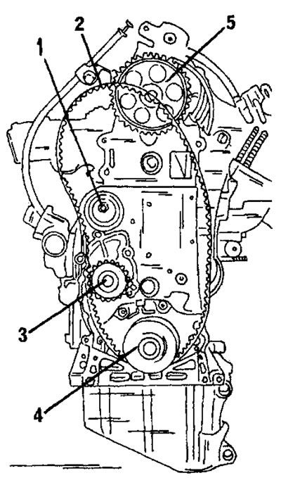
Figure 46. Front view of XU10 engine with timing belt removed. 1. Timing belt tension roller; 2. Toothed belt; 3. Water pump pulley; 4. Crankshaft toothed pulley; 5. Timing pulley of the camshaft
- From the front of the engine, remove the toothed pulley from the crankshaft. Behind the pulley there is a spacer washer and timing belt guide that should also be removed.
- Next to the water pump pulley there is a second plug for the main lubrication channel. Unscrew this plug (rod wrench).
- Loosen the 6 bolts securing the cover on the front side of the engine and remove the cover. After this, the engine looks as shown in Figure 49. Knock out the oil seal located there.
- Loosen the timing belt tension roller(s). The support pins should also be unscrewed.
- After removing the cover, remove the water pump located above it. The pump is secured with the bolts shown in Figure 50. In addition, it is necessary to remove the nearby water hose fitting and gasket.
- Loosen the engine mount bracket.
- Remove the cylinder head following the instructions already given above. Immediately mark the cylinder numbers on the top sides of the piston crowns so you don't forget to do this later.
- Turn the cylinder block over. The oil pan of these engines is mounted with or without a gasket.
- Unscrew the three oil pump mounting bolts from the bottom of the cylinder block. First lift and then pull the pump forward as indicated by the arrows in Figure 51. The water pump sprocket is removed together with the chain placed on it. There is a gasket plate between the oil pump and the cylinder block.
- Sequentially unscrew the nuts of the connecting rod bearing caps and remove the caps. To facilitate removal, install two bearings in the bottom dead center position. Remove the bearing shells from the journals and place them together with the connecting rod bearing caps. The connecting rods and bearing caps are marked in the locations shown in Figure 52. Push the pistons and connecting rods upwards out of the cylinder bores using a hammer handle. First check that the cylinder numbers are marked on the piston crowns. Remove the other two pistons/connecting rods in the same manner. After removal, immediately screw the bearing caps back onto the connecting rods (with bearing liners).
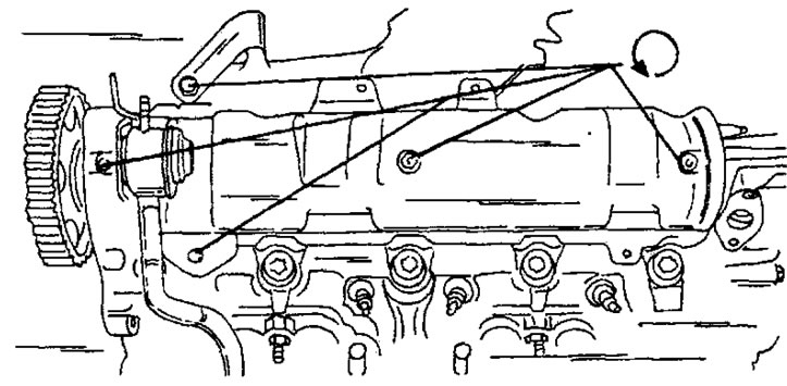
Figure 47. Cylinder head cover fastening is indicated by arrows (8-valve engine).
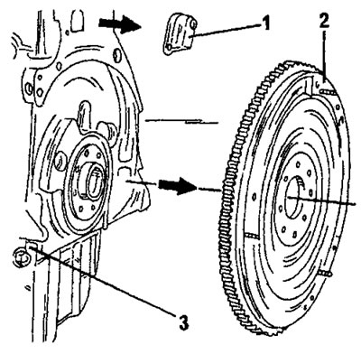
Figure 48. Removing the flywheel. 1. Sealing board; 2. Flywheel; 3. Blocking segment
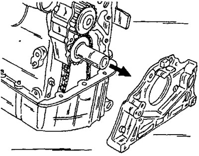
Figure 49. Removing the front cover.
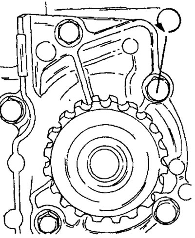
Figure 50. Installed water pump.
- Use a center punch to mark the relative positions of the main bearing caps and the cylinder block and, from the inside out, unscrew the ten bearing cap bolts and remove the caps. Immediately remove the bearing shells located underneath and assemble them together with the corresponding bearing caps. On one of the bearings (Figure 53) remove the two half washers that take up the axial play. When purchasing new bearing shells, be sure to indicate the year of manufacture and engine number, as modifications to the shells have been made.
- Remove the crankshaft and the remaining two half washers from the block. Immediately connect the liners together with the other liners and bearing caps. Also mark the places where the half washers were located. The rear crankshaft oil seal is removed together with the shaft and can be removed from the crankshaft.
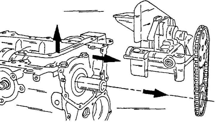
Figure 51. Removing the oil pump together with the chain and sprockets.
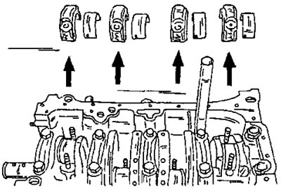
Figure 52. After marking the bearing caps and connecting rods, remove the bearing caps and liners.
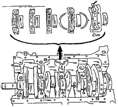
Figure 53. Assembling the main bearing caps, bearing shells and spacer washers on an XU engine (with or without working cylinder liners).
XU7 engines (with a working volume of 1.8 liters)
- Until the moment after removing the cylinder head, disassembly of these engines is carried out in a similar way. After this, the works differ.
- Remove the cylinder head as described above.
- Remove the clamping bars of the cylinder liners and mark the pistons and cylinder liners with a felt-tip pen.
- Loosen the nuts securing the connecting rod bearing caps, remove the bearing caps and remove each working sleeve together with the piston and connecting rod and lay them out in the order of installation. Remove the pistons and connecting rods.
- Remove the main bearing caps after marking the location of the caps in the engine crankcase.
- Remove the crankshaft and fold the upper halves of the bearings.