



Table of contents: 2.4.1 Removal 🠇 2.4.3 Disassembly and repair 🠇 2.4.3. Cylinder head assembly 🠇 2.4.4. Installing the cylinder head 🠇 2.4.5. Adjusting valve clearances 🠇
2.4.1 Removal
The cylinder head can be removed without removing the engine. These works have been described for various types of engines in section 2.2.
2.4.3 Disassembly and repair
TU type engines. Rocker shaft
The installation drawing of the rocker shaft is shown in Figure 90. The rocker arms of the intake and exhaust valves, as well as all springs located between them, must be marked identically in the event of their reinstallation. To disassemble the rocker shaft, remove the retaining ring at the end of the shaft and remove the parts from the shaft in the order they were installed.
Check the shaft and bore surfaces for wear and, if necessary, replace worn parts. Minor scratches can be removed with sandpaper. Blow out the rocker arm lubrication holes with compressed air.
When assembling the rocker shaft, the following points must be taken into account:
- Rocker arm supports #1 and #5 are the same. Both rocker arms have a centering pin that fits into a corresponding hole in the cylinder head, and a threaded hole for attaching the cylinder head cover.
- The three middle supports (No. 2, 3 and 4) are identical. They also have centering pins, but they lack studs.
- The rocker shaft assembly is carried out using figures 90 and 91 as follows:
- Generously lubricate all parts with engine oil, place a retaining ring on the end of the shaft and install the rocker arms and supports in the specified sequence, that is, put the spring and washer, the intake valve rocker arm, the exhaust valve rocker arm, and then the rocker arm block of the next pair of valves on the rocker arm shaft. After installation, secure the parts with a screw screwed into rocker arm block No. 1 (lower right section in figure 90). After assembly, compare the rocker arm mechanism with Figure 91 to ensure correct assembly. Place the assembled rocker shaft aside. Disassembling the cylinder head
- If not already done, remove the distributor and spark plugs.
- Unscrew the exhaust manifold heating shield and unscrew the eight nuts and washers of the exhaust manifold. Remove the manifold with two gaskets.
- Remove the intake manifold from the other side of the cylinder head.
- Loosen the bolt and remove the bracket from the distributor side. On the same side, unscrew the ignition distributor housing (5 bolts) and the cooling system box (3 bolts).
- While holding the camshaft timing pulley from turning, loosen the timing pulley mounting bolt. According to the instructions, the device shown in Figure 92 is used for this purpose. If there is no such device, you can insert a round rod into one of the holes of the toothed pulley and press it accordingly against the cylinder head. After this, move the bolt from its place and unscrew it. Remove the timing pulley from the end of the camshaft and remove the key. The key is removed with side cutters.
- Remove the oil seal from the other side of the cylinder head.
- Remove the camshaft retaining plate (1 bolt) and carefully pull the camshaft out of the cylinder head, avoiding the bearing journals or cams hitting the cylinder head components. Set the camshaft aside.
- Thoroughly clean all parts and inspect individual components as described below, replacing if necessary. If valve removal is necessary, follow the instructions in the next subsection.

Figure 90. Rocker shaft assembly drawing. The lower right section shows the screw that holds the parts together. The spacer ring is visible on the left.
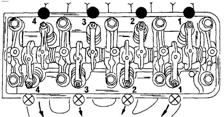
Figure 91. Assembled rocker arm mechanism. The inlet valves are marked with black circles, and the outlet valves are marked with circles with crosses.
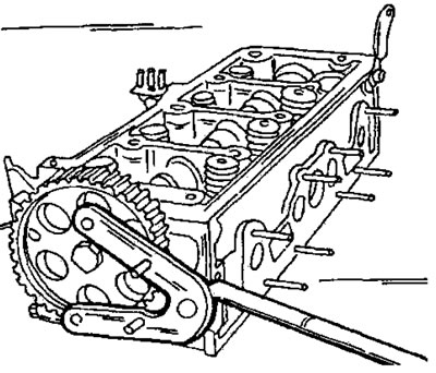
Figure 92. Loosening the camshaft toothed pulley bolt. Hold the toothed pulley as shown.
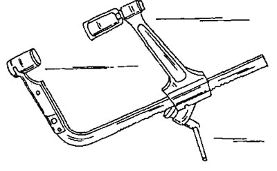
Figure 93. Valve puller.
Valves
To remove the valves from the cylinder head, a special valve puller is required. One such puller is shown in Figure 93, but it does not necessarily have to be of this type.
If you don't have a valve puller, you can also remove them as follows:
- Place a wooden block into the combustion chamber so that it rests against the valve being removed.
- Place a tube of the same diameter as the valve spring plate on the top side of the valve spring and hit the tube sharply with a hammer. In this case, the valve spring is compressed and both valve crackers pop out. The work is somewhat complicated due to the inclined position of the valves.
- Remove the parts from the valve and pull the valve out from the other side of the cylinder head. Immediately mark the location of the valve installation and set the valve aside accordingly.
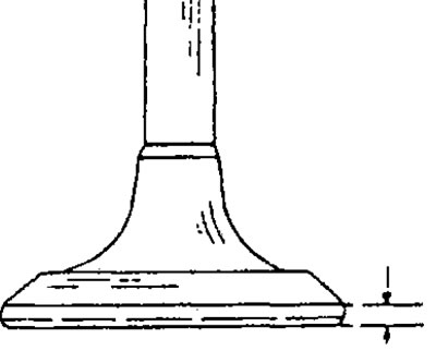
Figure 94. The thickness of the valve head, indicated by arrows, must not be less than the specified size.
Minor damage to valve surfaces can be repaired by lapping the valve in the seat, following the instructions in the "Valve Seats" subsection. Measure the valve to ensure it matches the dimensions and adjustments table, and replace any valves that do not meet the table's specifications.
If the ends of the valve stems are worn, they can be ground on a grinding machine, provided that the correction does not require removing more than 0.50 mm of material.
Valve heads can be ground on a grinding machine, provided that the thickness of the head, indicated by arrows in Figure 94, becomes no thinner than 0.5 mm.
Check the valve stems and, in this regard, the internal diameter of the valve guides, which requires a micrometer. To do this, measure the valve stems in several places, as shown in Figure 95, and record the measurement results. After this, measure the inner diameter of the valve guide bushings, as shown in Figure 96. If there is wear, that is, when the difference in measurement results is more than 0.10 mm, the valve guide bushings should be replaced (see subsection "Valve guide bushings").
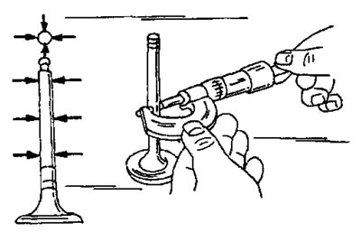
Figure 95. Measuring the valve stem diameter. The measurement locations are shown on the left.
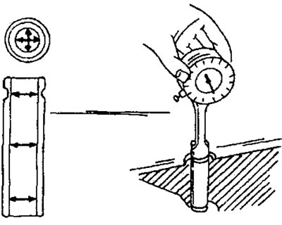
Figure 96. Measuring the inner diameter of the valve guide bushings. The measurement locations are shown on the left.

Figure 97. Milling the valve seat.
Valve seats
Check all valve seats for signs of wear or scarring. Light wear can be eliminated with a 45° cutter (exhaust valves) or 60° (intake valves). But if the seats already have significant wear, they should be re-milled or the valve seat rings need to be replaced. The final job requires drilling the valve seat holes and should therefore be performed at a Peugeot service center. When milling, keep in mind the difference in angles (intake valves 120°, exhaust valves 90°)
When installing new valve guides, additional milling of the valve seats is required. This requires an angle grinder (Figure 97), which is different for the intake and exhaust valves:
- Mill the corner of the valve seat and then lightly mill the top side of the seat with a trim cutter to reduce the valve seat width to 1.45 mm for intake valves and 1.8 mm for exhaust valves. Once this width is reached, the milling work is completed.
- Lapping the machined valve seats. To do this, rub in a little grinding paste and insert the valve into the corresponding seat. Place a suction cup on the valve and move the valve in both directions as shown in Figure 98.
- After lapping, carefully remove any remaining dirt and paste from the parts and check the valve seat on the valve head and in the seat ring. Both pieces should show a continuous matte ring that defines the width of the saddle.
- Apply a few strokes on the valve head ring with a pencil. Apply strokes around the circumference at intervals of approximately 1 mm. Then, carefully lower the valve into the seat and rotate the valve 90°, applying slight pressure.
- Remove the valve and check if the pencil marks have been removed from the valve seat. If the valve seat width is within the specified limits, the head can be installed on the vehicle. Otherwise, the valve seats will need to be treated or, in the worst case, the cylinder head will need to be replaced. In this case, it is necessary to remove all parts from the old cylinder head and transfer them to the new head.

Figure 98. Valve grinding.
Valve springs
For perfect control, it is necessary to have a spring testing device to check the length of the spring under load. If such a device is not available:
- Compare a used spring with a new spring. To do this, clamp both springs in a vice and slowly close the vice. If the springs are compressed to approximately the same degree, then this is a sure sign that both springs are approximately the same. If the old spring compresses shorter than the new spring, this is a sign of spring fatigue and all springs should be replaced as a set.
- Place all springs on a smooth surface in sequence (glass board) so that the closed loop is located at the bottom. Place a steel square next to the spring. Measure the gap between the square and the top of the spring; it should not exceed 2.0 mm. Otherwise, the spring is warped.
- Measure the free length of the spring as shown in Figure 99. Although there is no precise data available, it can be assumed that the springs are suitable for reinstallation if they are all approximately the same length.
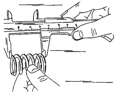
Figure 99. Measuring the length of an unloaded spring.
Valve guide bushings
To accurately measure valve guides and valve stems, a micrometer is required, the use of which is shown in Figures 95 and 96. If the difference between the two measurements exceeds 0.10 mm, the corresponding valve guide must be replaced (or all guides) If a micrometer is not available, the valve stem clearance in the guide bushings can also be determined as follows:
- Clean the valve guides by pulling a rag soaked in gasoline through the bottom in both directions. Also, thoroughly clean the valve stems and then insert the valves into the corresponding holes.
- Place a dial indicator on a stand on the top side of the cylinder head and press the valve out of the hole until the end of the valve stem is flush with the guide sleeve on the other side of the cylinder head.
- Move the valve head from the top side in both directions and read the dial indicator. If the reading exceeds 1.0 - 1.2 mm, it is most often necessary to replace the guide bushing.
- Before replacing the valve guide, check the general condition of the cylinder head. Cylinder heads with small cracks between the valve seats can be ground, provided that the cracks are really small.
- To replace the valve guide, press out the old guide using a suitable punch. To press out the guide bushings, it is necessary to heat the cylinder head in hot water. Before pressing out, measure the height of the guide sleeve protrusion above the cylinder head surface. The neck at the end of the drift should be machined so that it fits into the guide bushing.
- When replacing the guide bushings, the valves are also replaced at the same time. After this, it is necessary to grind the valve seats. There are guide bushings with increased diameters, accordingly, it is necessary to drill the receiving holes for the guides in the cylinder head.
- Generously lubricate the guide bushings with engine oil and press them into the cylinder head to the protrusion value measured before removing the old guide bushing.
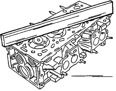
Figure 100. Checking cylinder head tilt. Insert the dipstick into the place indicated by the arrow.
- After pressing in, ream the valve guide bushings to a diameter of 7.00 mm ±0.022 mm. Use an adjustable reamer for this. This automatically creates the required clearance of the valve stems in the guide bushings.
- When replacing the valve guide, milling of the valve seats is required.
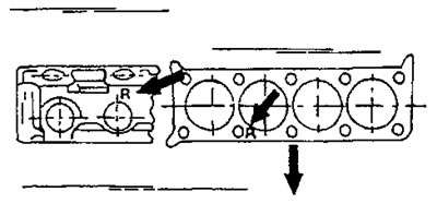
Figure 101. Location of the "R" marking on the cylinder block and on the cylinder head gasket.
Cylinder head
- Thoroughly clean the cylinder head and cylinder block surfaces and check for distortion of the cylinder head surface. To do this, place a measuring ruler along, across and diagonally on the surface of the cylinder head and use a feeler gauge to measure the clearance between the ruler and the cylinder head. If the feeler gauge passes through a thickness of more than 0.05 mm, as shown in Figure 100, the cylinder head should be given for flat milling. If the clearance is greater in any place, the cylinder head must be replaced.
- The cylinder head can be milled if it is necessary to remove metal no more than 0.02 mm, however, the following features should be taken into account.
- Some cylinder blocks have an "R" marking in the location shown in Figure 101. This means that the cylinder block has already been milled to an oversize size. With this type of cylinder block, when installing the cylinder head, a thicker cylinder head gasket must be installed, which also has an "R" marking in the specified location. If it turns out that milling of such a cylinder head is required, you should contact a Peugeot service station.
Camshaft
- Camshafts are not the same on all engines and the correct camshaft must be installed when replacing. The camshaft is held on the cylinder head surface by a mounting plate. The plate fits into the groove in the camshaft and thus fixes its position.
- To remove the camshaft, use side cutters to pull out the key and unscrew the mounting plate. Carefully pull out the camshaft, without hitting the camshaft lobes or bearings on the support bushings.
- Place the camshaft with its end journals in the prisms, as shown in Figure 102, or clamp it in the centers of a lathe and place the measuring probe of the dial indicator against the middle journal of the bearing. Slowly turn the camshaft and read the dial indicator scale. If the reading exceeds 0.01 mm, the shaft is bent and must be replaced.
- Check the bearing journals for visible damage. If damage is detected, further work may not be carried out.
- To measure the axial clearance of the camshaft, insert it into the cylinder head and secure it with a mounting plate. Place the cylinder head on a flat surface. Place a dial indicator on the front side and move the shaft in both directions. If the play is more than 0.16 mm, the mounting plate is worn and should be replaced. In the worst case, the camshaft flange may be worn out, which means that it is necessary to carefully check the parts to avoid replacing the camshaft in vain.
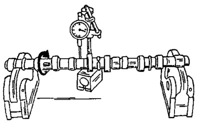
Figure 102. Checking camshaft runout.
XU-type engines
- Screw a suitable clamp onto the exhaust manifold studs and clamp this clamp in a powerful vice. Naturally, first unscrew the eight manifold nuts and remove the four gaskets.
- Unscrew the complete intake unit together with the throttle body. The six screws must be unscrewed and the hoses disconnected.
- Draw a line along the top of the distributor and the distributor housing to ensure that the distributor is subsequently installed in its original position (both studs are installed in the same position in the slot of the distributor plate). Unscrew the two nuts and remove the distributor. The ignition distributor mounting is shown in Figure 103.
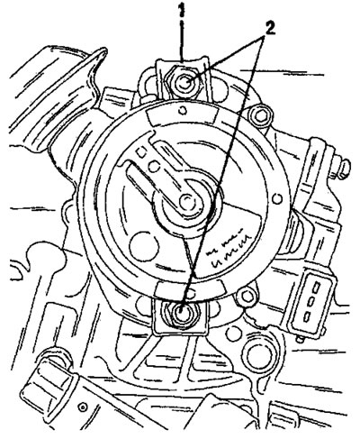
Figure 103. Mark the installation position of the ignition distributor at location (1) before unscrewing the nuts (2).
- Completely unscrew the housing located behind the distributor together with the parts installed in it (7 bolts).
- Lock the camshaft timing pulley accordingly (Figure 92) and unscrew the bolt. Remove the bolt, washer and timing pulley.
- Press the oil line in the middle of the cylinder head.
- Loosen the ten camshaft bearing cap nuts evenly and from the outside to the center. Mark the installation position of the covers and remove the covers sequentially.
- Sequentially pull the valve lifters out of the holes. It is necessary to mark the tappets according to their installation position. This can be done as shown in Figure 104. Remove the inserted adjusting washers and place them next to the corresponding tappets.
- Remove the valves following the instructions for TU engines. Each valve guide has an oil seal located in the cylinder head intake bore. Remove the caps with tweezers. During assembly, the oil deflector caps must be replaced.
Valves
Minor damage to the valve heads can be repaired by lapping the valves in the cylinder head seats, as described in the "Valve Seats" subsection. Measure the valves against the dimensions and adjustment table and replace any valves whose dimensions do not match the table.
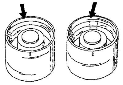
Figure 104.
- If the ends of the valve stems are worn, they can be processed on a grinding machine, provided that no more than 0.50 mm of material is removed for correction.
- The valve head can be ground on a valve grinding machine, provided that the thickness of the valve head, indicated by the arrows in Figure 94, after grinding is not less than 0.5 mm.
- Check the valve stems and, along with them, the diameter of the valve guides, for which a micrometer is required. To do this, measure the valve stems in several places, as shown in Figure 95, and record the measurement results. After this, measure the inner diameter of the corresponding guide bushing, as shown in Figure 96. If wear is detected, i.e. the difference is more than 0.10 mm, the guide bushings should be replaced (see the subsection "Valve Guides"). The nominal diameter of the valve stems/valve guides is 8.0 mm.
Valve seats
- Check all valve seats for signs of wear or scarring. Minor signs of wear can be removed with a 45° milling cutter. However, if the seats are already significantly worn, they should be re-milled or the valve seat rings will need to be replaced. The latter work requires drilling the valve seat holes and should therefore be carried out at a Peugeot service station.
- When installing new valve guides, additional milling of the valve seats is required. This requires an angle grinder (Figure 97). In this case, the work is carried out in the same way as described for TU type engines, but the inlet and outlet valves correspond to an angle of 45a.
Valve springs
Valve springs are checked in the same way as on TU-type engines. Identical springs are installed on the intake and exhaust valves.
Valve guide bushings
To accurately measure the valve guides and valve stems, a micrometer is required, as shown in Figures 95 and 96. All inspection procedures are performed in the same way as on TU-type engines. However, replacing the guides is performed differently.
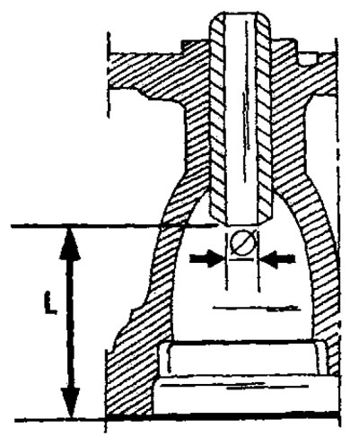
Figure 105. Dimension "L" determines the installation height of the valve guides on XU type engines.
- To replace the valve guide, press out the old guide using a suitable punch. To press out the guide bushings, it is necessary to heat the cylinder head in hot water. Before pressing out, measure the height of the guide sleeve protrusion above the cylinder head surface. The neck at the end of the drift should be machined so that it fits into the guide bushing.
- When replacing the guide bushings, the valves are also replaced at the same time. After this, it is necessary to grind the valve seats. There are guide bushings with increased diameters, accordingly, it is necessary to drill the receiving holes for the guides in the cylinder head.
- Generously lubricate the guide bushings with engine oil and press them into the cylinder head to the size measured before removing the old guide bushing. This dimension is measured using Figure 105 and should be 40.0 mm for the intake valves and 33.0 mm for the exhaust valves.
- After pressing in, ream the valve guide bushings to a diameter of 8.00 mm ±0.022 mm. Use an adjustable reamer for this. This automatically creates the required clearance of the valve stems in the guide bushings.
- When replacing the valve guide, milling of the valve seats is required.
Cylinder head
- Thoroughly clean the cylinder head and cylinder block surfaces and check for distortion of the cylinder head surface. To do this, place a measuring ruler along, across and diagonally on the surface of the cylinder head and use a feeler gauge to measure the clearance between the ruler and the cylinder head. If the feeler gauge passes through a thickness of more than 0.05 mm, as shown in Figure 100, the cylinder head should be given for flat milling. If the clearance is greater in any place, the cylinder head must be replaced.
- The cylinder head can be milled if it is necessary to remove metal no more than 0.02 mm, however, the following features should be taken into account.
- Some cylinder blocks are marked with the letter "R" in the location shown in Figure 101. This indicates that the cylinder block has already been milled to an oversize size. With this type of cylinder block, a thicker cylinder head gasket, also marked "R," must be installed when installing the cylinder head. This gasket is 0.2 mm thicker. If milling of this type of cylinder head is required, please contact a Peugeot service center.
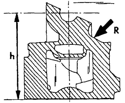
Figure 106. Location of the "R" marking on an oversized cylinder head. The height of the cylinder head is measured between the "h" ancestors.
Before deciding whether the cylinder head can be reinstalled, the height of the cylinder head ("h", Figure 106) between the contact surfaces is measured. The height should be 141 mm (on 8-valve engines) and 140.75 mm (on 16-valve engines).
Camshaft
- The camshafts are not necessarily the same on all XM10 type engines and the correct camshaft must be installed when replacing.
- Place the camshaft with its end journals in the prisms, as shown in Figure 102, or clamp it in the centers of a lathe and place the measuring probe of the dial indicator against the middle journal of the bearing. Slowly turn the camshaft and read the dial indicator scale. If the reading exceeds 0.01 mm, the shaft is bent and must be replaced.
- Check the bearing journals for visible damage. If damage is detected, further work may not be carried out.
- Check the bearing journals and bores for visible damage. Qualified inspection requires precise measurement of bearing bores and journals. The nominal diameter of the bearing holes and support journals is the same, the difference lies in the tolerance zone. To measure bearing bores, screw on the bearing caps and tighten them to the specified tightening torque.
- To measure the axial clearance of the camshaft, insert it into the cylinder head and secure it with a mounting plate. Place the cylinder head on a flat surface. Place a dial indicator on the front side and move the shaft in both directions. If the clearance is more than 0.07 - 0.15 mm, then there is wear on the surface of the camshaft support or cylinder head. This means that one or both parts need to be replaced.
- Only in the worst case scenario is there wear on the camshaft flange.
2.4.3. Cylinder head assembly
If the cylinder head is replaced, the distributor, spark plugs, temperature switches, etc. are transferred from the old cylinder head to the new one. Thoroughly clean all parts and generously lubricate all moving and rotating parts with engine oil.
TU type engines
- Insert the valves into the guide bushings. If the valve seats have been ground, they should be installed in the corresponding seats in the cylinder head. The same applies to re-installed valves, which must be put back in their original locations.
- Using Figure 107, install new valve stem seals on each valve guide.
- Push in the valves (generously lubricated with motor oil) from the bottom of the cylinder head and place the parts shown in Figure 108 on them from the top. To do this, place springs on each valve and compress them with a valve puller.
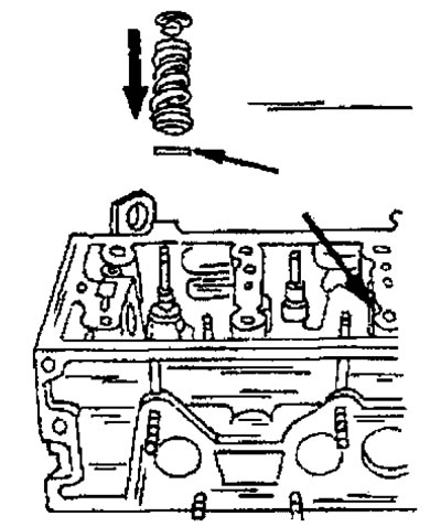
Figure 107. Installing oil deflector caps on valve guide bushings.
1. Oil deflector cap; 2. Installation tube
When the end of the valve stem begins to protrude from the top of the valve spring plate, insert crackers with sharp tweezers. Slowly release the valve puller and check if the crackers are held securely in the valves.
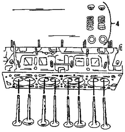
Figure 108. Installing valve parts. Don't forget to put the washer indicated by the arrow.
- Tap the top of each valve stem with a plastic hammer. Loosely seated crackers will pop out. As a precaution, place a rag on the ends of the springs to prevent the parts from flying apart.
- Lubricate the camshaft journals with engine oil and carefully insert the shaft into the cylinder head, without hitting the cams or journals on the bearing bushings.
- Screw the shaft mounting plate onto the cylinder head. Check the axial play of the camshaft again. If the axial play is within the norm, tighten the mounting plate fastening to a torque of 16 Nm.
- Lubricate the outside of the new oil seal with engine oil and press it into the cylinder head. You can use a piece of pipe for pressing, but do not damage the seal.
- Place the timing pulley on the camshaft so that the key engages with the groove in the timing pulley, and carefully drive the pulley onto the camshaft. Lock the camshaft properly and tighten the bolt to 80 Nm.
- Install the cooling system box on the cylinder head. If necessary, install the thermostat and thermostat housing cover first. Cover the contact surface of the housing with a sealing compound and install the housing. Tighten the three bolts to 8 Nm. Screw in the temperature switches.
- Install the distributor drive housing in the same manner. Here the fastening is done with 5 bolts.
- Cover the intake manifold with sealing compound, place it on the cylinder head and tighten evenly six times to a torque of 8 Nm.
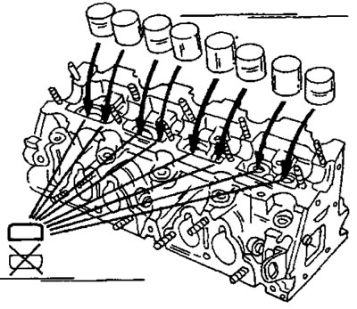
Figure 109. Cylinder head assembly.
- On the other side of the cylinder head, apply two exhaust manifold gaskets, install the manifold, and evenly tighten the 8 nuts to a torque of 16 Nm. Screw in the manifold heater shield.
- Install the ignition distributor 8 in accordance with the instructions in the relevant section.
- All other work is carried out in reverse order. After final installation, valve clearances are adjusted.
XU-type engines
- Install the valve stem seals as shown in Figure 107. The piece of tubing should have a diameter of 8 mm. Be careful not to damage the valve stem seals (damage increases oil consumption).
- Install the valves in the manner described for TU engines. As shown in Figure 109, spring cups are installed under the springs. Valve springs are installed on the cylinder head with the flat side. The intake and exhaust valve crackers are the same.
- Generously lubricate the tappets and adjusting washers with engine oil and install the parts in their original places. The washers are flat on one side. This side of the washer is on the end of the valve stem, as shown in Figure 110. This is extremely important.
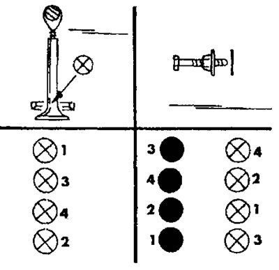
Figure 110. Generously lubricate the tappets and adjusting washers with engine oil and install the parts into the holes. Pay attention to the installation of adjusting washers (bottom left).
- If the tappet has to be pulled out, it should be pulled out completely to check the position of the adjusting washer, as the washer may shift when the tappet is pulled out.
- Lubricate the camshaft bearing journals with engine oil and insert the shaft into the cylinder head. Install the same type of lids in accordance with the markings. Tighten the bearing caps crosswise from the inside out.
- After adjusting the valve clearances (see section 2.4.5 for the relevant engine) press in the camshaft oil seal using the appropriate tube.
- Install the camshaft timing pulley, lock the shaft properly and tighten the bolt to a tightening torque of 35 Nm.
- Further assembly is carried out in reverse order.
2.4.4. Installing the cylinder head
The installation of the cylinder head was described in detail during engine assembly in section 2.3.1 for TU type engines and in section 2.2.1 in the relevant subsections for other engines and therefore no repeat description is required.
2.4.5. Adjusting valve clearances
Valve clearance adjustment is performed only on TU, XII7 and XU10 type engines with 8 valves. The 16-valve XU10 engine has hydraulic valve lifters, which means no valve clearance adjustment is required.
Control and adjustment work is described separately for each engine type.
TU type engines
If the adjustment is made on the engine installed in the vehicle, which is usually the case during a general valve clearance check, then a number of preliminary steps must be performed to ensure access to the valves. To do this, it is necessary to remove the cylinder head cover and all associated work, such as removing the air filter, disconnecting certain hoses, etc. When removing the cylinder head cover, ensure that the two spacers and the oil drain shield are located above the rocker arms, which also need to be removed. There are two methods used to check and adjust valve clearances, both of which are described below.
Turn the engine until the exhaust valve of the first cylinder is fully open. In this position, adjust the intake valve of the third cylinder and the exhaust valve of the fourth cylinder. To easily turn the engine, lift the front wheel, engage 5th gear and turn the wheel until the engine is in the desired position. The second wheel must be on the ground. To relieve compression, you can screw in the spark plugs.
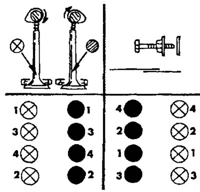
Figure 111. Adjusting valve clearances.
Crank the engine until the next exhaust valve opens. The valve adjustment is carried out in accordance with the table below and using Figure 111, which also shows the positions of the camshaft cams.
| The exhaust valve is fully open | #Adjust the intake valve | Adjust the exhaust valve |
| 3 | 4 | 2 |
| 4 | 2 | 1 |
| 2 | 1 | 3 |
The exhaust valves are marked with circles with a cross, and the intake valves are marked with black circles. When opening the corresponding inlet valve, adjust the valves indicated on the right side.
Adjusting the valve clearances can also be done in another way, when the engine is turned until both valves of the first cylinder are completely closed. This position can be controlled by the fourth cylinder, the valves of which must intersect. When turning the engine from this position in both directions, it is visible that one valve of the fourth cylinder rises and the other valve falls. In this position, the rocker arms have clearances and both camshaft lobes are in the position shown in Figure 112. After adjusting the valve clearances of the first cylinder, the engine is turned another half turn and the next pair of closed valves is adjusted. The following table shows the valve clearance adjustment diagram:
| Intersecting valves | Valves to be adjusted |
| cylinder No. 1 | cylinder No. 4 |
| cylinder No. 3 | cylinder No. 2 |
| cylinder No. 4 | cylinder No. 1 |
| cylinder No. 2 | cylinder No. 3 |
To check the valve clearance, insert a feeler gauge of the required thickness between the end of the valve stem and the rocker arm, as shown in Figure 113. To adjust the clearances of the intake valves, a feeler gauge of 0.20 mm thickness is required; to adjust the exhaust valve clearances, you need a 0.40 mm thick feeler gauge. The clearance tolerance for all valves is ±0.05 mm. The feeler gauge should fit easily, but not too loosely, into the gap. A sign of good adjustment is when the feeler gauge enters without jamming, bends slightly, and then fits into the gap between the valve stem and the rocker arm.
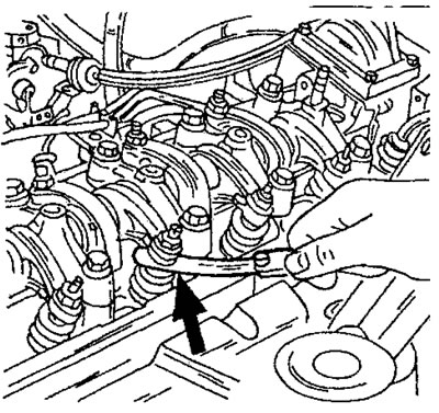
Figure 113. Insert the feeler gauge into the gap indicated by the arrows between the end of the valve stem and the adjusting screw. Tightening torque of the lock nut: 18 Nm (tU type engines).
When adjusting the valve clearance, use a socket wrench to loosen the lock nut and a screwdriver to turn the adjusting screw. When tightening the lock nut, hold the adjusting screw to prevent it from coming loose. Tighten the nuts to a torque of 18 Nm.
Finally, check the clearances of all valves once again.
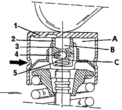
Figure 114. Sectional view of hydraulic tappet (16-valve engine). References to digital and letter designations are given in the text.
XU-type engines
The valves of the 16-valve engine do not require adjustment, since this engine is equipped with hydraulic valve lifters. To explain the operating principle of these pushers, a brief description is given with reference to Figure 114:
- Oil is supplied under pressure from the cylinder head and fills chamber (A) of the tappet (1), and from there it enters the low-pressure chamber (B). This opens the ball valve (4) and fills chamber (C).
- The piston (2) and the working sleeve (3) are supported by a spring (5). This maintains mechanical contact between the cam and the valve stem. A slight leak between the piston and the working sleeve allows air to escape from the pusher.
- When, during the rotation of the camshaft, one of the cams of the shaft presses on the tappet, the oil pressure in chamber (C) increases. The ball valve is pressed against the support and the cam stroke is transmitted to the valve.
- If adjustment of an 8-valve engine is required without removing it from the vehicle, a number of preliminary works must be carried out to provide access to the valves. This involves removing the entire air cleaner/cylinder head cover assembly, which was described in removing the cylinder head.
- Raise the front of the car on one side and engage fifth gear. This allows you to turn the engine during adjustment using the raised wheel.
- Mark and disconnect the spark plug wires and remove the spark plugs.
- Prepare a table to record the measured valve clearances as shown in Figure 115.
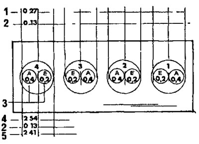
Figure 115. Valve clearance check table.
Turn the raised front wheel in the forward direction to turn the engine. To measure the valve clearance, the camshaft cam corresponding to the given valve must be directed upwards, that is, the other valve of the same cylinder is open. The first cylinder is located on the flywheel side and is marked "A" in Figure 115. Measure the clearance by inserting a feeler gauge between the cam back and the valve tappet, as shown in Figure 116.
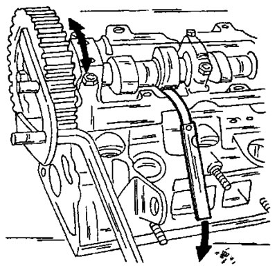
Figure 116. Measuring valve clearances. For clarity, the cylinder head is shown in a removed position.
Enter the measurement result in column 1 of the table, in our example 0.27 mm.
Turning the engine half a turn in the direction of engine operating rotation, measure the clearances of all valves and enter them into the table in accordance with the example. The specified value for intake valves is 0.15–0.25 mm, and for exhaust valves, 0.35–0.45 mm. If the valve clearances are outside the specified limits, adjust them by installing adjusting shims of a different thickness between the valve lifters and valve stems. A larger clearance requires a thicker washer, while a smaller clearance requires a thicker washer. Figure 117 shows the adjustment process.
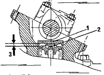
Figure 117. Sectional view of camshaft and valve tappet. 1. Valve lifter; 2. Adjusting washer; 3. Thickness of the adjusting washer
If adjustment is required:
Remove the wheel well shield to gain access to the end of the crankshaft.
Remove the upper and lower timing belt covers.
To lock the timing drive, insert the locking pin (round rod) at approximately the 11 o'clock position into the hole in the belt pulley.
Loosen the timing belt tensioner bolt, press the tensioner away from the belt and remove the timing belt from the camshaft toothed pulley.
Press the oil pipe from the top of the camshaft.
Remove the ignition distributor.
From the front of the cylinder head, remove the 6mm Allen head bolt and loosen the nuts of the five camshaft bearing caps evenly and crosswise. First loosen the camshaft bearing nuts on the flywheel side.
Remove the remaining camshaft bearing caps and take out the camshaft. The oil seal must be replaced.
Remove the first valve lifter and the adjusting washer located underneath it, clean the adjusting washer, and measure its thickness. The thickness of the new adjusting washer is determined as follows:
- Correction: measured gap minus specified gap value. From Figure 115 it is clear how the calculation is carried out.
- The amendment can be positive or negative. With a positive correction, a thicker washer should be installed; for a negative correction, a thinner washer must be installed.
- The average value from the tolerance field is taken as the specified value.
- Thickness of new washer = measured thickness of washer + correction.
- Select a new adjusting washer whose thickness is closest to the calculated one. The thicknesses of the existing shims range between 2.225 and 3.550 mm. Degrease the new shim before measuring and installing.
- Proceed in the same way with the remaining valves, the clearance of which must be adjusted.
- Before installation, lubricate the adjusting washers with engine oil and insert them into the recess in the spring cup. Figure 110 shows the installation of washers.
- When replacing the camshaft or tappets, be sure to install 2.25 mm thick washers (nominal thickness) regardless of what washers were installed previously.
- Lubricate with engine oil and install the tappets. After installation, the tappets must not be lifted, as this may cause the adjusting washers to shift. If the push rod has been lifted slightly, it should be pulled out to reinsert the adjusting washer.
- Lubricate the camshaft bearings with engine oil and install them so that the 4th and 6th cams (counting from the flywheel side) fit into the corresponding pushers. In Figure 118, both cams are indicated by arrows.
- Cover the bearing cover contact surfaces on the distributor side with sealing compound "Auto Joint" and put the lid on. Also install the caps of the remaining bearings in accordance with the numbers.
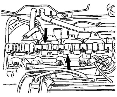
Figure 118. Both indicated cams should be in contact with the pushers with their backs.
- Tighten the caps evenly and consistently from the inside outward to a final tightening torque of 15 Nm. Also insert the bolt into the distributor housing and tighten
- Press a new oil seal into the cylinder head using a piece of pipe of the appropriate diameter. Do not deform the seal. Since space is limited, you can take a piece of pipe with a large washer and press the seal in using a long bolt.
- Place the toothed pulley on the camshaft and, holding the shaft from turning, screw in the bolt and tighten to a torque of 35 Nm.
- Turn the camshaft (very slowly) at least two turns and measure the valve clearances again. Make adjustments if necessary.
- Installation of the remaining parts is carried out in reverse order. It should be noted that the bolt shown in Figure 119 must be installed with a new sealing washer. Tighten the bolt to a torque of 15 Nm. Install the oil pipe (2) in Figure 119 from the top of the cylinder head. Install the air cleaner/cylinder head cover assembly in accordance with the instructions section on installing the cylinder head. The belt installation description is given separately.

Figure 119. Tighten the bolt indicated in place (1) with a new sealing washer and tighten to a torque of 15 Nm. The oil pipe (2) is inserted.