
English Русский
Български
Беларускі
Український
Српски
Hrvatski
Română
Polski
Slovenský
Magyar
Bookmark Articles Sitemap Contacts
Company Hyundai Company Opel Company Skoda Company Kia Company Mitsubishi Company LADA Company Audi
PeugeotBook.ru


Series 100   Series 200   Series 300   400-500   Series 600   Crossovers   Others
 
Peugeot 305 (1977-1989) Peugeot 306 (1993-2002) Peugeot 307 (2001-2008)

General information about the ignition system (Peugeot 306)

  • Main
  • 30X
  • Peugeot 306 (1993-2002)
  • Gasoline engine
  • Ignition system
  • General information about the ignition system
0
Depending on the engine type, year of manufacture, etc., either an ignition distributor or an ignition coil with four connectors may be installed instead of a distributor. The sole function of this element, considered as a "voltage distributor", is to distribute high voltage to the spark plugs in accordance with the firing sequence. This is achieved by a dual, four-port ignition coil mounted on the flywheel side of the cylinder head, where the distributor would normally be located.

The primary ignition voltage is supplied by a control unit that is common to the ignition system and the fuel injection system. Primary voltage is supplied alternately to both parts of the ignition coil.

A four-output ignition coil mounted at the end of the cylinder head is used in the same way. It converts low voltage into secondary high voltage for the spark plugs. For every revolution of the engine, two sparks are produced, one at the end of the compression stroke and one at the end of the exhaust stroke. The latter is of course not used. Cylinders No. 1 and No. 4 form one pair, and cylinders No. 2 and No. 3 form another pair.

The ignition timing is adjusted according to the programmed parameter field and is adjusted depending on the engine speed and load. The current position of the crankshaft is determined by a sensor near the flywheel. Other factors that determine ignition timing are throttle position, coolant temperature, and absolute pressure.

The flywheel has a ring gear around its circumference that is missing two teeth at an angle of 180°, so that the dead center sensor accurately determines the moment of passing the top and bottom dead centers and transmits a signal to the control unit. Figure 174 shows the flywheel with the sensor on the right side.


The ignition coil simply screws on and off.
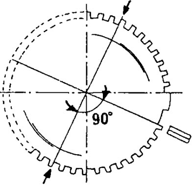
Figure 174. Flywheel with two missing teeth on the ring gear.

Figure 174. Flywheel with two missing teeth on the ring gear.


Thus, the ignition system installed on most engines consists of the following elements:
  • The sensor is installed in the flywheel housing. This sensor sends a signal to the control unit that corresponds to the required moment of spark formation.
  • An electronic control unit that also operates in the fuel injection system.
  • Ignition system control unit.
  • Ignition coil or ignition distributor.
  • On 16-valve engines, a position sensor is installed on the cylinder head. It is tuned to a specific camshaft cam for the intake valves and determines the top dead center position of the first cylinder (once per working cycle, that is, every two revolutions).

The ignition system determines the ignition timing in the cylinders according to the data stored in the memory, which in turn is compared with the data coming from the sensor at the flywheel (engine speed and current flywheel position), air flow meter (engine load), sensor in the air flow meter (air temperature) and a sensor in the cylinder head (coolant temperature). The throttle switch provides information about the throttle position during engine starting, idle, full load and engine braking. The spark generation signal is transmitted from the ignition/fuel injection system control unit via the ignition switch to the ignition coil control.


On a 16-valve engine, the distributor, driven by the camshaft, distributes high voltage to the spark plugs in the firing sequence. On this engine, both ignition modules are electrically connected to the control unit. Both modules are connected to four coils (one module for two ignition coils). Ignition coils are mounted directly on the spark plugs instead of the conventional spark plug caps. Therefore, there are no high-voltage spark plug wires.

When working with wires or connectors of the ignition system and the associated fuel injection system, it is necessary to turn off the ignition. This will prevent possible short circuit.

Information copied from the resource (www.PEUGEOTBOOK.ru)
This article is available at russian, bulgarian, belarusian, ukrainian, serbian, croatian, romanian, polish, slovak, hungarian
Article reviewed by editor: Shirokov Arseny
Share information:
Previous
Peugeot 306: Ignition system
Next

 
Spark plugs
Ignition timing
See similar information for other Peugeot models

➨ Ignition system check Peugeot 106 (1991-2003)
➨ General information about the ignition system of the TU5 petrol… Peugeot 207 (2006-2014)
➨ Checking the ignition system (40,000 km/2 years) Peugeot 405 (1987-1997)
➨ Ignition System — General Information and Precautions Peugeot 605 (1989-2000)
➨ Fuel injection and ignition system. 2.0-liter turbocharged engine Peugeot 806 (1994-2002)
Link to this article in different formats
Comments and feedback from visitors
No comments yet


Add two numbers 46 + 27


Peugeot 307 (2001-2008) 
  • User manual
  • Keys, doors and alarm
  • Controls and instruments
  • Driving and operation
  • Maintenance
  • Power unit
  • Petrol engines TU3 and TU5
  • Petrol engines EW10
  • Diesel engines DV10
  • Diesel engines DW10
  • Transmission
  • Clutch and drive shafts
  • Mechanical gearbox
  • Automatic gearbox
  • Chassis, running gear
  • Front suspension
  • Rear suspension
  • Steering
  • Brake system
  • Body and interior
  • Exterior (external elements)
  • Interior (internal elements)
  • Doors, locks and windows
  • Heating and air conditioning
  • Electrical equipment
  • Equipment and devices
  • Power devices
  • Airbags
  • Electrical circuits
Peugeot 306 (1993-2002) 
  • General information
  • Introduction to manual
  • Specifications
  • Gasoline engine
  • Engine repair
  • Lubrication system
  • Cooling system
  • Fuel injection
  • Ignition system
  • Diesel engine
  • Engine repair
  • Lubrication system
  • Cooling system
  • Fuel injection
  • Transmission
  • Clutch
  • Gearbox
  • Drive shafts
  • Chassis, running gear
  • Steering system
  • Front suspension
  • Rear suspension
  • Brake system
  • Electrical equipment
  • Power devices
  • Electrical circuits
Peugeot 305 (1977-1989) 
  • General information
  • Maintenance
  • Power unit
  • Gasoline engines
  • Diesel engines
  • Cooling system (gasoline)
  • Cooling system (diesel)
  • Fuel system (gasoline)
  • Fuel system (diesel)
  • Ignition system
  • Transmission
  • Clutch
  • Mechanical gearbox BB8
  • Mechanical gearbox BE1
  • Automatic gearbox ZF4
  • Shafts, hubs and wheels
  • Chassis, running gear
  • Brake system
  • Car suspension
  • Steering
  • Body and interior
  • Exterior (external elements)
  • Interior (internal elements)
  • Electrical equipment
  • Equipment and devices
  • Headlights and lighting
  • Power devices
  • Electrical circuits
  • Wiring diagrams (diesel)
PeugeotBook.ru © 2018–2026 | Mobile version | Sitemap: EN BG BY UA RS HR RO PL SK HU | Write message | Site search | Add to bookmarks | Peugeot owners
106 (1991-2003) | 206 (1998-2012) | 207 (2006-2014) | 305 (1977-1989) | 306 (1993-2002) | 307 (2001-2008) | 405 (1987-1997) | 406 (1995-2004) | 605 (1989-2000) | Partner-I (1996-2008) | Eurovans-807 (2002-2014) | Eurovans-806 (1994-2002) | J5 (1981-1993) |
Cookies are used to ensure the correct display of pages on the site.