



11.2.1 Removal
- Although wheel bearings can be replaced with the steering knuckle installed, it is much easier to remove the steering knuckle and replace the bearings on a workbench. The wheel bearing must be replaced if the wheel hub has been removed from the steering knuckle for any reason.
- Apply the handbrake and engage first gear.
- Loosen the wheel nuts.
- Remove the brake pads and brake caliper. Hang the brake caliper on a piece of wire on the body so that it does not put tension on the brake hose.
- Loosen the tie rod ball joint nut and press the steering tip ball pin with a suitable puller.
- Remove the drive shaft following the instructions section 9.1, without disconnecting it from the gearbox. Push the drive shaft to the side and suspend it from the body with a piece of wire so that it does not sag and does not come out of the gearbox.
- Loosen and carefully knock out the ball joint pin clamp bolt from the bottom of the steering knuckle. Remember which side the bolt head is on.
- Carefully press the transverse lever downwards with a pry bar to disengage the ball joint pin from the lower end of the steering arm. The wishbone can also be released from the ball joint by unscrewing the bolts shown in Figure 220. In this case, the ball pin remains on the steering knuckle.
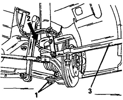
Figure 220. Removing the steering knuckle. Bolts (1) secure the ball joint plate to the wishbone 1. Bolts; 2. Tie bolt; 3. Tie rod end puller
- Insert the special tool shown in Figure 214 or the mentioned rod wrench into the tension spline on the top side of the steering knuckle and spread the spline so that the steering knuckle can be pulled down. Before removing the wheel bearing, immediately clean the steering knuckle thoroughly.
11.2.2 Replacing wheel bearings
Wheel bearings are a rigid fit on the wheel hubs and require a hydraulic press to replace.
- Unscrew the two brake disc mounting bolts and remove the brake disc from the wheel hub.
- Wipe the inside of the steering knuckle with a clean cloth to release the retaining ring and remove it with special pliers, as shown in Figure 221.
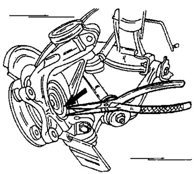
Figure 221. Removing the retaining ring from the rear of the steering knuckle (the figure shows the installed steering knuckle).
Removing the hub or wheel bearing requires removal tools. If they are not available, you can press out or perhaps knock the hub off the steering knuckle. An appropriate support must be placed under the steering knuckle. The parts shown in Figure 222 form the wheel hub and wheel bearing.
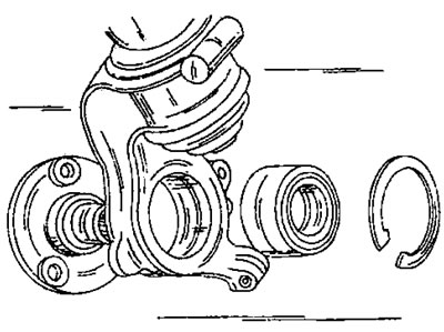
Figure 222. Wheel bearing and wheel hub removed from the steering knuckle. The retaining ring is located on the inside.
The inner bearing race remains on the hub and can be pulled out. This is required in all cases, since the bearing is being replaced. To press out the bearing, you need a puller whose jaws are positioned under the bearing ring. When the center bolt of the puller is tightened, the bearing ring comes out. Figure 223 shows the Peugeot puller.
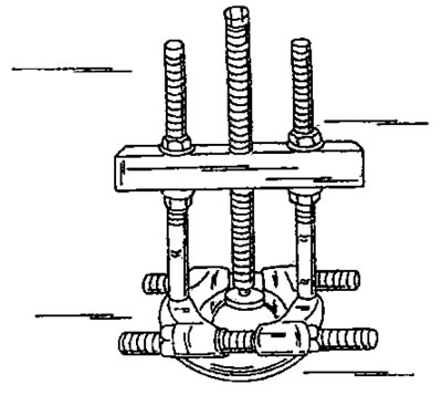
Figure 223. Removing the inner bearing ring from the wheel hub using a special puller.
The new bearing is inserted together with the pressed-in seal and plastic ring on the inside. Both parts are not removable. Once the seal is removed, the bearing cannot be used further. The plastic ring is released when the wheel hub is pressed in and can then be removed.
The wheel bearing is installed as follows:
- To press in the bearing, use a piece of pipe with the same diameter as the diameter of the outer ring of the bearing. Press the bearing ring into the steering knuckle until it stops.
- Check the position of the separator in the bearing hole and insert the retaining ring using special pliers. If the retaining ring is bent when removed, it should be replaced. Check the position of the ring around the entire circumference.
- Press the wheel hub into the steering knuckle using a press. In this case, place the bearing and steering knuckle under it accordingly. The press lining (2) in Figure 224 must rest against the inner ring of the wheel bearing. Place the press punch (1) against the outer surface of the hub. At the same time, the plastic ring comes out.
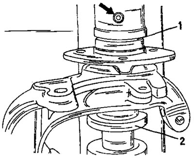
Figure 224. Pressing in the wheel hub. Before lowering the punch (1), place a lining (2) under the inner ring of the bearing.
11.2.3 Installation
- As described when installing the shock absorber strut, install the steering knuckle into the front wheel suspension. Perform all the steps described in section 11.1 work until the steering knuckle is secured to the shock absorber strut.
- Insert the ball joint pin from the bottom of the steering knuckle and fully compress the parts. Insert the bolt from the designated side and tighten the connection. If the ball joint plate has come loose, tighten the bolts to 50 Nm.
- Connect the steering rod to the steering arm. The ball joint must be degreased. Tighten the new self-locking nut to 35 Nm.
- Thoroughly clean both sides of the brake disc and screw on the brake caliper. Cover the bolt threads with Loctite. Alternately tighten both bolts to a final tightening torque of 110 nm if Bendix brakes are installed, or to 120 nm if ATE Teves brakes are installed. With these brakes, tighten the brake cylinder on the mounting frame with a tightening torque of 30 nm.
- Further details on installing the brake caliper are contained in the relevant section.
- Install the drive shaft into the wheel hub following the instructions section 11.2. Tighten the shock absorber strut and steering knuckle clamping joint to a torque of 55 Nm.
- The final tightening of the nut is done after lowering the vehicle. In this case, the nut is tightened with a torque of 265 Nm (m20 thread) or 325 nm (m24 thread).
- Lower the vehicle and tighten the wheel nuts to the specified torque (85 Nm).