



The steering knuckle must be removed, that is, either the shock absorber strut or the entire suspension must be removed, as described above. After this, the wheel bearings are replaced as follows:
- Press the wheel hub out of the steering knuckle. This can be done in various ways. Either the steering knuckle is placed under a press and the wheel hub is pressed out from the rear, or a universal press is used, as shown in Figure 143. In this case, the middle bolt of the press should rest against the outer diameter of the hub, that is, a round plate should be placed under this bolt, transmitting pressure to the hub. Tighten the middle bolt until the hub comes out.
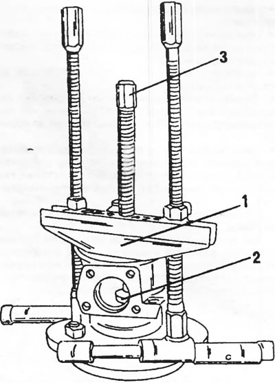
Figure 143. The wheel hub is pressed out of the steering knuckle using a puller (1). A thrust washer (2) is placed on the hub to transfer the pressure of the puller bolt to the hub.
- Apply the steering knuckle accordingly and knock out the bearings (2) and (5) on the inside in Figure 144. Both oil seals (1) and (6) come out together with the bearings.
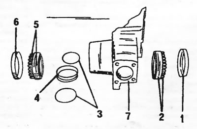
Figure 144. Details of the disassembled steering knuckle. 1. Seal, internal; 2. Inner wheel bearing; 3. Adjusting washers; 4. Bearing spacer ring; 5. Outer wheel bearing; 6. Seal, external; 7. Steering knuckle
- Remove the bearing spacer ring and both adjusting washers from the inside of the steering knuckle.
- Knock out the outer bearing rings from the opposite side of the steering knuckle.
All parts must be thoroughly cleaned and checked. The seals must be replaced.
The steering knuckle is assembled as follows. Below is a description of the work using a special tool. If the work is carried out without it, the description can be skipped.
- Press the outer bearing rings into the steering knuckle (conical surfaces outward). Without damaging the work surfaces.
Adjust the bearing clearances. This work must be carried out very carefully, as incorrectly adjusted bearings quickly deteriorate. The bearing clearance should be between 0.025 and 0.10 mm.
- Insert and press the well-lubricated bearing (6) in Figure 145 into the inside of the steering knuckle. For this, use the guide insert (8) and rod (9).
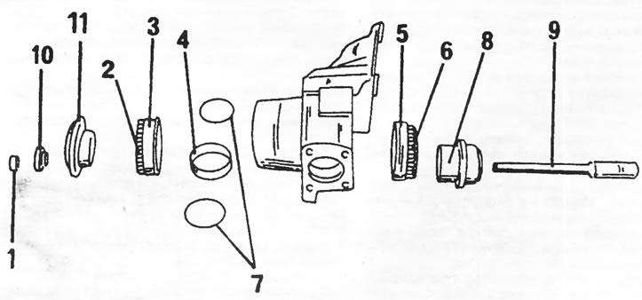
Figure 145. Assembling the steering knuckle and wheel bearings using special tools. 1. Nut; 2. Wheel bearing, outer; 3. Outer bearing ring; 4. Bearing spacer ring; 5. Bearing ring, inner; 6. Wheel bearing, inner; 7. Adjusting washers; 8. Emphasis; 9. Tie rod; 10. Emphasis; 11. Emphasis
- Insert the bearing spacer ring (4) between the two adjusting washers (7) into the outer side of the steering knuckle. The parts are centered using the guide insert (8).
- Insert a well-lubricated inner wheel bearing (2) from the other side and insert both inserts (10) and (11) into the hole. Screw the nut (1) onto the rod and tighten it to a torque of 10 Nm.
- Place a spanner on the nut and turn the wheel bearings several times to install them.
Note: If the mentioned special tool is not available, a long bolt can be used. The wheel bearings can be pressed instead of parts (10) and (11) with the corresponding wrench heads, and then large washers and a nut can complete the adjustment device.
After this, the bearings are adjusted. The following description again mentions special tools, but any dial indicator on a suitable stand can also be used.
- Clamp the steering knuckle in a vice as shown in Figure 146 and, using the dial indicator's feeler gauge, reset its scale to zero.
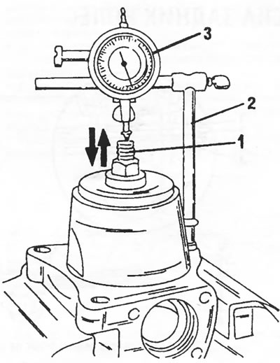
Figure 146. Checking the axial play of bearings. Mount the dial indicator (3) on the stand (2) so that the dial indicator's feeler gauge is placed against the inserted bolt (1). As the bolt moves in the direction of the arrows on the scale, the bearing play is indicated.
- Move the bolt (1) up and down, taking readings from the dial indicator scale. Readings should be between 0.025 and 0.10 mm.
- If the clearance is outside the permissible values, the thickness of the washers (7) in Figure 145 should be changed. Washers of different thicknesses are available.
- Remove the measuring device and take out the bearings again.
- Lubricate well and insert the bearing (5) in Figure 144. Press the seal (6) into place along the edge.
- Place the steering knuckle onto the hub and press the wheel bearing together with the steering knuckle onto the hub. For pressing, a piece of pipe is used, which is placed on the inner ring of the bearing.
- Insert the adjusting washer, bearing spacer ring and second adjusting washer into the steering knuckle from the inside.
- Insert the inner ring of the bearing block (2) in Fig. 144 (well lubricated) and press it with a piece of pipe of the appropriate diameter. Lubricate and press in the new oil seal (1) to the edge.