



The inner ends of the wishbones are bolted to the front crossmember of the frame.
A jet thrust is installed between the transverse lever and the console on the chassis. It is attached to the wishbone with bolts and is connected to the chassis via rubber bushings in the console. Adjusting washers are installed in the rubber suspensions to correct the longitudinal inclination angle of the kingpin.
Figure 134 shows a section of the front wheel suspension with the location of individual parts.
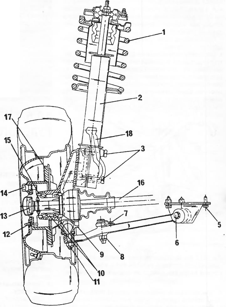
Figure 134. Section of the front wheel suspension. 1. Coil spring; 2. Shock absorber strut; 3. Bolts, 125 Nm; 4. Rubber support; 5. Bolt, 50 nm; 6. Bolt, 90 Nm; 7. Bolt, 25 Nm; 8. Nut, 140 nm; 9. Bolt, 50 nm; 10. Wheel bearing adjusting washers; 11. Nut, 100 nm; 12. Bolt, 15 nm; 13. Wheel hub nut, 50 Nm; 14. Wheel bolt, 180 Nm; 15. Wheel bearing (diameter depending on design); 16. Drive shaft; 17. Brake disc; 18. Steering linkage lever
The drive shaft runs in two bearings on the inside of the steering knuckle. The bearings are tightened during assembly of the steering knuckle using compensation washers to ensure the prescribed axial play of the wheel bearings. It should be noted that the diameter of the wheel bearings on the models under consideration is not the same.
You can find the original on the resource: PEUGEOTBOOK