



Table of contents: 11.1.1. Removal 🠇 11.1.2. Disassembling the shock…🠇 11.1.3. Assembling the shock…🠇 11.1.4. Installing the shock…🠇
11.1.1. Removal
Before disassembling the shock absorber, the coil spring must be compressed. The wheel can either remain on the hub or can be removed. The latter case provides better access to the mounting points.
- Apply the handbrake and engage first gear. Loosen the wheel nuts.
- Place the front of the car on stands and remove the front wheel. Place a garage jack under the front axle.
- Loosen the three nuts of the upper shock absorber strut support.
- Unscrew the four bolts of the lower shock absorber mount. The bolts are marked with arrows in Figure 135.
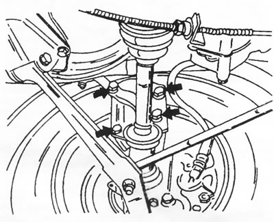
Figure 135. The shock absorber strut is attached to the steering knuckle with four bolts, indicated by arrows. The steering knuckle, wishbone, etc. remain on the wheel suspension when the shock absorber strut is removed.
Slowly lower the jack until the top of the shock absorber strut is free and separate the shock absorber strut from the steering knuckle. Pull the shock absorber strut back as a set. Never loosen the nut in the middle of the shock absorber support, as this will cause the shock absorber to fall apart. If you intend to disassemble the shock absorber strut, you can only loosen the nut on the installed strut, but tighten it again before pulling out the shock absorber strut.
11.1.2. Disassembling the shock absorber strut
Only the coil spring, the complete shock absorber strut, the shock absorber strut bearing or small parts can be replaced. The shock absorber strut itself cannot be disassembled.
To relieve the spring force when unscrewing the upper support of the shock absorber strut, a spring compressor is required.
Never attempt to loosen the nut in the middle of the shock absorber support without first reliably compressing the spring. Figure 136 shows a special spring compression device used at service stations. Two hooks with a screw mechanism between them can also be used. In this case, the hook should cover four or five turns of the spring.
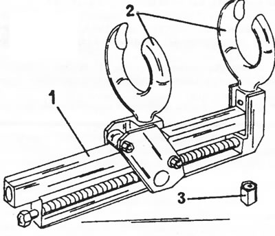
Figure 136. Special device for compressing springs for disassembling the shock absorber strut.1. Tie; 2. Paws; 3. Nut
- Clamp the shock absorber strut mounting plate in a vice.
- If you have the special device shown in Figure 136, install it as shown in Figure 137.
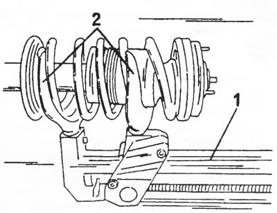
Figure 137. Place the spring compression device (1) on the shock absorber strut. Both paws (2) grip the spring coils.
- Tighten the tensioner bolt until the spring is compressed.
- While holding the piston rod with a socket head cap screw wrench as shown in Figure 138, loosen the piston rod nut.
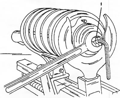
Figure 138. Loosen the piston rod nut (1) while holding the piston rod with a hexagon socket head cap screw wrench.
- Remove the nut, upper support cup and needle thrust bearing, as well as the stop from the upper side of the shock absorber bearing, as shown in Fig. 139. Remove the rubber cushion (1).
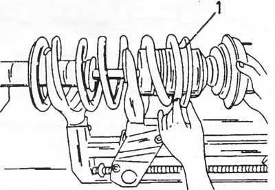
Figure 139. Removing the upper support of the shock absorber strut and the rubber cushion (1) of the spring.
Remove the shock absorber strut from the compressed spring.
When using the spring compression hooks, tighten the screw mechanism to release the spring from the upper and lower cups, i.e. the spring should be able to move slightly. Only after this should you unscrew the support nut.
The rubber bump stop, rubber tip and its washer, bronze bushing, needle roller bearing, sealing ring, second needle roller bearing of the shock absorber bushing support, i.e. parts 3,4,5,6 in Figure 140, must be replaced if their unsatisfactory condition is established during disassembly of the shock absorber strut. When handling the shock absorber, do not damage the shock absorber piston rod.
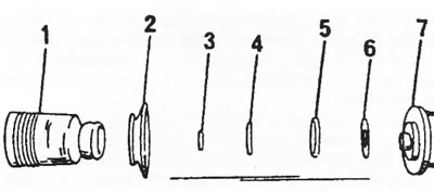
Figure 140. Details of the upper part of the shock absorber strut. Parts 3,4,5,6 must be replaced during disassembly. 1. Protective cuff; 2. Spring cup; 3. Bronze bushing; 4. Needle roller bearing; 5. Sealing ring; 6. Needle roller bearing; 7. Upper shock absorber strut support
11.1.3. Assembling the shock absorber strut
Before assembling the shock absorber strut, it is necessary to prepare the upper support for installation. It is assumed that the mentioned parts are being replaced.
- Place the spring cup vertically and knock the thrust needle roller bearing off the cup using a small chisel or a powerful screwdriver.
- Place the spring cup with the smaller diameter side down and knock the bronze bushing off it.
- Lubricate the parts and press in a new bronze bushing on the same side.
- Insert a new needle roller bearing as shown in Figure 141. If the bearing is difficult to insert, you can gently tap it with a rubber or plastic hammer.
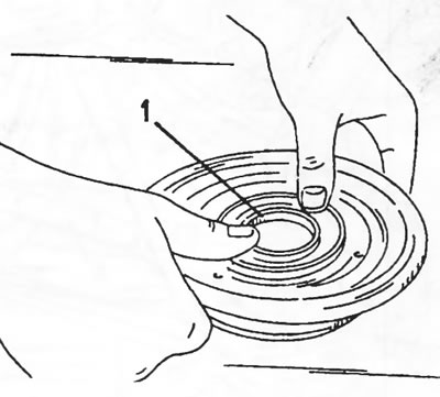
Figure 141. Installing the needle roller bearing (1) into the spring cup.
- Insert the rubber bumper into the inside of the spring cup and put on the sealing ring.
- Insert the needle roller bearing guide washer into the spring cup and install the upper shock absorber mount.
- Clamp the shock absorber strut in a vice and pull the shock absorber piston rod out of the shock absorber strut as far as possible.
- Place a spring compressor on the spring and compress the spring. When using a special device, the distance between its paws should be 90 mm.
- Place the compressed spring on the piston rod and place the guide ring on the spring.
- Slide the prepared shock absorber support onto the piston rod.
- Install the washer and screw a new self-locking nut onto the piston rod, tightening it to a torque of 70 Nm. While doing this, hold the piston rod as shown in Figure 138. Service stations use a special tool and a torque wrench to hold the piston rod. When using an open-end wrench, it is not possible to install a torque wrench, so the tightening torque must be determined by eye. You can also tighten the nut firmly and check with a torque wrench with a socket. In this case, since the nut is tightened, the piston rod can no longer turn.
- Slowly release the spring while checking the position of the spring.
11.1.4. Installing the shock absorber strut
The installation of the shock absorber is carried out in the reverse order, taking into account the following points:
- Insert the shock absorber strut with the support studs from the bottom side of the shock absorber strut niche and screw on three nuts from the top side without tightening them. Since the nuts are self-locking, they must be replaced.
- Raise the entire suspension with a jack and screw in the four shock absorber mounting bolts. Tighten the bolts evenly in a circle with a tightening torque of 125 Nm.
- Tighten the upper shock absorber strut support nuts in a circle with a tightening torque of 15 Nm.
- All other work is carried out in reverse order. Wheel bolts are tightened to a torque of 180 Nm.