



Note: To avoid damaging the hub cap, it must be removed using a puller. A damaged cap must be replaced.
- Loosen the wheel nuts and carefully knock off the hub cap using a powerful screwdriver or a small chisel. If access to the cap is difficult, first remove the wheel. In this case, then reinstall the wheel and lower the vehicle.
- Loosen the hub nut.
- Raise the front of the car and support the body with stands.
- Remove the wheel.
- The front wheel suspension is shown in Figure 142. The suspension is removed using this figure.
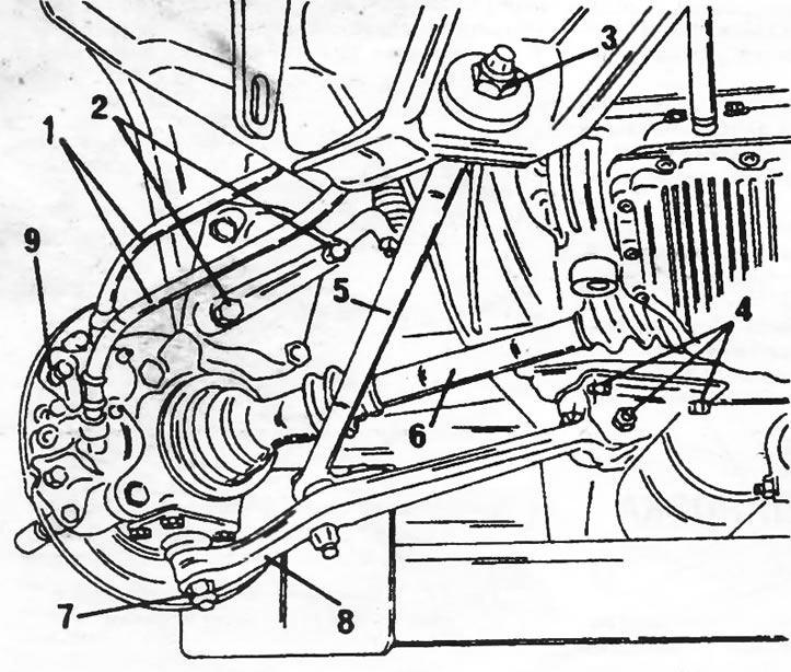
Figure 142. View of the front suspension after removing the wheel. 1. Brake hoses; 2. Steering knuckle arm bolts; 3. Reactive thrust nut; 4. Transverse arm mounting bolts; 5. Jet thrust; 6. Drive shaft; 7. Ball joint; 8. Suspension wishbone; 9. Brake caliper
- Disconnect the brake hoses (1) from the brake pipes on the chassis. To prevent dirt from getting in, close the brake hoses and pipes with appropriate plugs.
- Loosen the steering knuckle arm bolts (2) and remove the arm. The steering rod may not be removed.
- Unscrew the nut (3) from the rear side of the reaction rod. Save all washers.
- Loosen the bolts (4) securing the transverse arm from the inside (non-support finger).
- Loosen the three nuts of the upper shock absorber strut support. Support the suspension as it may fall after the last nut is removed.
- Pull the suspension out, while doing so it is necessary to properly remove the reaction rod and drive shaft. If it is necessary to remove the drive shaft, follow the instructions section 9. Otherwise, pull the steering knuckle off the end of the drive shaft.
(Information posted on the website: «peugeotbook»)
The front suspension is installed as follows:
- Insert the shock absorber strut from below and insert the studs into the holes in the upper shock absorber strut mount. Screw on the nuts and tighten them to a tightening torque of 15 Nm.
- Pull the front suspension outward and slide the drive shaft into the steering knuckle and wheel hub.
- Install the wishbone mounting console, insert the bolts and tighten them to a torque of 50 Nm.
- Insert the jet thrust into the console on the body (check that all parts are installed), place washers and screw on the nut. Tighten the nut (3) in Fig. 142 to a torque of 100 Nm.
- Place the steering knuckle arm onto the steering knuckle and tighten the mounting bolts to a torque of 125 Nm.
- Connect the brake hoses to the brake pipes. After this, it is necessary to remove air from the brake system in accordance with the instructions in the section "Brake system".
- Put the wheel on and lower the car.
- Apply Loctite to the hub nut threads and screw the nut on. Tighten the nut to 50 Nm. Then install the hub cap.
- Finally, tighten the wheel bolts to a torque of 180 Nm.