



The inner ends of the wishbones are bolted to the front crossmember of the frame.
An anti-roll bar is installed between both wishbones. It is connected on each side by rods with shock absorber struts.
Figure 212 shows the location of the wishbones and anti-roll bar.
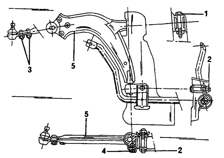
Figure 212. Location of the transverse arm and stabilizer rod on one side of the vehicle. The ball joint can be turned away from the wishbone (bolts "3").1. Bolt, 75 Nm; 2. Bolt, 55 Nm; 3. Bolt, 50 nm; 4. Bolt, 27 Nm; 5. Wishbone.
Before doing any work on the front suspension, it is worth emphasizing some important details now:
- The upper shock absorber mounts on vehicles with manual steering and on vehicles with power steering have different mounting positions.
- The thread size at the ends of the drive shafts on vehicles with 1A-liter engines is 20 mm (M20). The wheel bearing diameter on this steering knuckle is 72 mm. If the vehicle is equipped with an ABS system, the parts listed below are installed.
- On all other vehicles, the thread size at the ends of the drive shafts is 24 mm (M24). On these vehicles, the wheel bearing diameter is 82 mm, and if the vehicle is equipped with an ABS system, the parts listed below are also installed.
- The stabilizer link diameter is not the same on all vehicles. When replacing the stabilizer link (for example, after an accident) you should purchase the required part.
- The drive shafts operate in a single bearing on the inside of the steering knuckle, but as noted, the wheel bearing diameters on the models in question are not the same.