



Table of contents: 11.1.1. Removal 🠇 11.1.2. Disassembling the shock…🠇 11.1.3. Assembling the shock…🠇 11.1.4. Installing the shock…🠇 Location of the upper shock absorber…🠇
11.1.1. Removal
Before disassembling the shock absorber, the coil spring must be compressed. At Peugeot service stations, a special clamping device is used for this purpose, as shown in Figure 216. If such a device is not available, the spring can be compressed with two hooks until the upper and lower spring supports are released. Place the hooks of the tensioning device on three or four turns of the spring. In addition, a special device is required to loosen the steering knuckle spline. However, in this case, you can also use a precisely fitting rod wrench. The use of such a key is described below.
- Apply the handbrake and engage first gear. Loosen the wheel nuts.
- Place the front of the car on stands and remove the front wheel.
- Compress the spring to the point where you feel that the spring is free.
- Unscrew the parts in the order of the numbers shown in Figure 213.
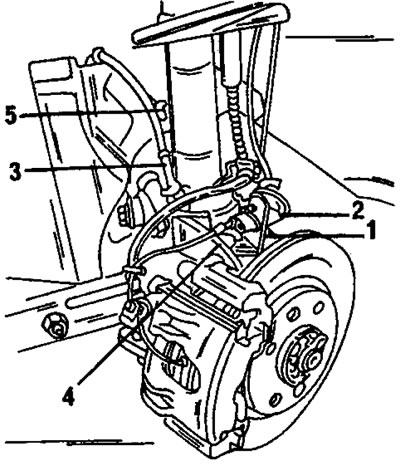
Figure 213. To remove the shock absorber strut, unscrew the parts in the order of the numbers indicated. 1. Holder; 2. Connecting the brake hose; 3. ABS sensor wire (if any); 4. Bolt; 5. Stabilizer link nut
- Loosen the lower shock absorber strut mounting nut.
- Insert the said tool or rod wrench into the slot of the steering knuckle as shown on the left side of Figure 214, and then move it upward as shown on the right side of Figure 214. The key is automatically locked in the upper position. At the same time, the clamping spline expands.
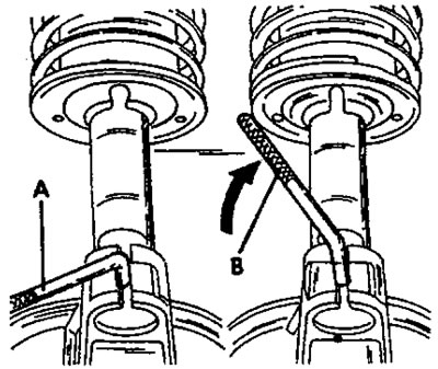
Figure 214. To expand the tie spline, insert the special key into the tie spline as shown in view "A" and then move it upwards as shown in view "B".
- Carefully press the steering knuckle and wishbone downwards with a pry bar to release the upper side of the steering knuckle from the lower end of the shock absorber strut, as shown in Figure 215.
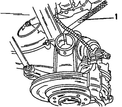
Figure 215. After expanding the tension spline, use the key (1) to press the steering knuckle down.
- Push the drive shaft to the side and tie it to the body with a piece of wire so that it does not come out of the gearbox.
- Unscrew the two upper shock absorber mount bolts from the inside of the engine compartment. Have an assistant support the shock absorber strut from the bottom until the last nut is loosened. Never loosen the nut in the middle of the shock absorber support, as this will cause the shock absorber to fall out. If you intend to disassemble the shock absorber strut, you can loosen the nut before removing the strut, and then tighten it again before removing the strut. After this, the shock absorber strut is pulled downwards.
11.1.2. Disassembling the shock absorber strut
Only the coil spring, the complete shock absorber strut, the shock absorber strut bearing or small parts can be replaced. The shock absorber strut itself cannot be disassembled.
To relieve the spring force when unscrewing the upper support of the shock absorber strut, a spring compressor is required.
Never attempt to loosen the nut in the middle of the shock absorber support without first reliably compressing the spring. Figure 216 shows a special spring compressor used at Fteugeot service stations. Two hooks with a screw mechanism between them can also be used. In this case, the hook should cover four or five turns of the spring. If you have a special device for compressing springs, secure it in a vice.
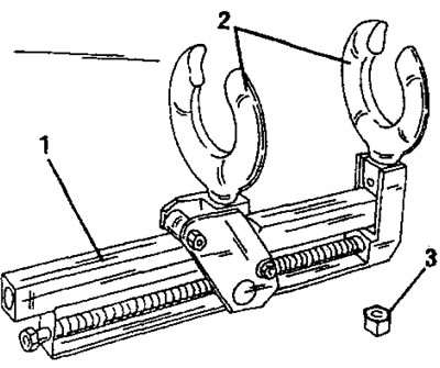
Figure 216. Special device for compressing springs for disassembling the shock absorber strut. 1. Tie; 2. Lala; 3. Nut
Disassembly of the shock absorber strut is carried out as follows:
- Tighten the tensioner bolt until the spring is compressed.
- While holding the piston rod with a socket head cap screw wrench as shown in Figure 217, loosen the piston rod nut.
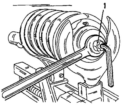
Figure 217. Loosening the piston rod nut while holding the piston rod with a hexagon socket head cap screw wrench.
- Remove the nut, upper thrust cup and needle bearing, and the thrust bearing top end of the shock absorber bearing.
- Remove the shock absorber strut from the compressed spring.
- Remove the parts from the shock absorber strut one by one and place them in the order of installation.
- When using the spring compression hooks, tighten the screw mechanism to release the spring from the upper and lower cups, i.e. the spring should be able to move slightly.
- The rubber bumper, rubber tip and its washer, and rubber bushing must be replaced. When handling the shock absorber, do not damage the shock absorber piston rod.
11.1.3. Assembling the shock absorber strut
- Place the spring vertically and place the removed parts on top of it one by one. The upper shock absorber bearing must be correctly positioned all the way around. Section 11.1.4 specifies the differences between a vehicle with manual steering and a vehicle with power steering. The spring can be installed in any way around the circumference.
- Place the assembled spring into the tensioner.
- Insert the rubber bumper into the protective cover with the larger diameter of the bumper facing up.
- Place the rubber bump stop assembly with protective cover on the shock absorber strut and put the washer on top.
- Compress the spring in the tensioner until the piston rod passes through from the top side.
- Place the bearing insert, spacer washer and new nut on the piston rod.
- Slowly release the spring while checking the position of the spring.
- After installing the shock absorber strut (in accordance with the instructions in the next section) tighten the piston rod nut to a torque of 45 Nm. While doing this, hold the piston rod from turning with a wrench. At Peugeot service stations, a special tool is used to hold the piston rod with a torque wrench. When using a spanner, the tightening torque can naturally only be determined by eye. You can also tighten the nut and then check the tightening torque by using a socket with a torque wrench. The nut must be tightened so that the piston rod can no longer turn.
11.1.4. Installing the shock absorber strut
The installation of the shock absorber is carried out in the reverse order, taking into account the following points:
- Insert the shock absorber strut with the support studs from the bottom side of the shock absorber strut niche and screw in two bolts from the top side without tightening them.
- Raise the car with a jack, remove the support from the side where work is not being performed.
- Lower the car with a jack. The side without the stand should be lowered onto the wheel, and the side where the work is being done should be lowered onto the stand. In this way, the action of the anti-roll bar can be used to connect the shock absorber strut to the steering knuckle.
- If the special tool shown in Figure 214 has been removed, reinsert it into the steering knuckle clamp spline and turn it a quarter turn.
- Raise the entire suspension and insert it into the lower end of the shock absorber. The steering knuckle should go up to the stop. The shock absorber strut has a guide that must fit into a slot. In addition, there are two stops on the shock absorber strut that should fit against the top side of the steering knuckle.
- To close the spline, turn the special tool shown in Figure 214 back a quarter turn.
- Remove the drive shaft from the suspended wire.
- Drive a bolt into the steering knuckle and shock absorber strut and tighten the nut slightly.
- Install the wheel and lower the vehicle.
- Make sure once again that the shock absorber fits perfectly against the steering knuckle. To do this, you should inspect the area shown in Figure 218. If this is not the case, slightly loosen the bolt and nut of the connection. In this case, the shock absorber strut is completely immersed in the steering knuckle. After this, tighten the nut to a torque of 55 Nm.
Source available here: PeugeotBook
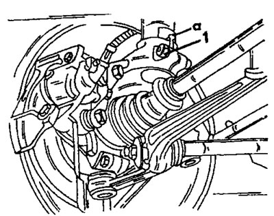
Figure 218. Check whether the shock absorber strut is fully seated at location (a). If not, loosen and retighten bolt (1).
- Tighten the upper shock absorber strut support nuts to a tightening torque of 20 Nm.
- Connect the anti-roll bar links. Tighten the nut to a torque of 40 Nm.
- The above mentioned bolts are shown in Figure 219.
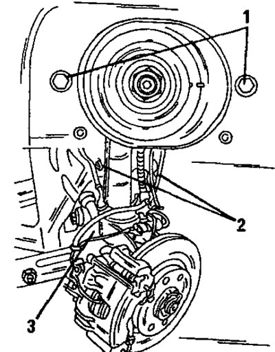
Figure 219. The most important tightening moments when installing the shock absorber strut. 1. Bolts, 20 nm; 2. Rod nuts, 40 Nm; 3. Tie bolt, 55 Nm
- All other work is carried out in reverse order. If the brake hose has come loose, bleed the air from the brake system.
Location of the upper shock absorber strut support
The upper support of the shock absorber strut has a protrusion on one side, which must be directed differently, depending on whether the vehicle has power steering. With mechanical steering, this protrusion on the left shock absorber strut should point to the right. If the vehicle has power steering, the protrusion should be located on the left side. On the right shock absorber strut the location of the protrusion is mirrored. This should be taken into account when assembling the shock absorber strut.