



- Loosen the wheel nuts and raise the rear of the vehicle on stands. Do not place a stand under the rear axle on the side where the spring will be removed.
- Remove the wheel.
- Trace the brake hose routing and unscrew the brake hose from the brake pipe. To do this, unscrew the union nut and disconnect the tube. Knock out the leaf spring and remove the hose together with the metal fastener. To prevent dirt from getting in, close the hose and tube with appropriate plugs.
- Place a jack under the axle tube on the side where the spring is being removed and raise the axle slightly.
- Unscrew the bolts and nuts shown in Figure 150 and knock the spring U-bolts down with a hammer, being careful not to damage the threads.
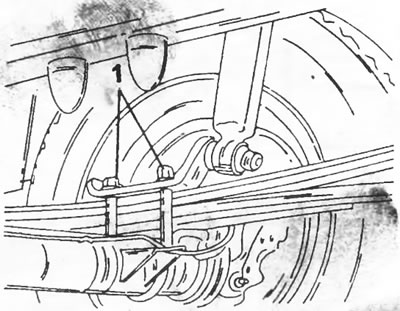
Figure 150. Fastening the rear spring to the axle tube. The nuts (1) are secured with sheet metal locking. It is necessary to replace the locking element.
- Unscrew the two nuts shown in Figure 151 from the rear side of the spring, and the spring pin nut from the front side from the inside.
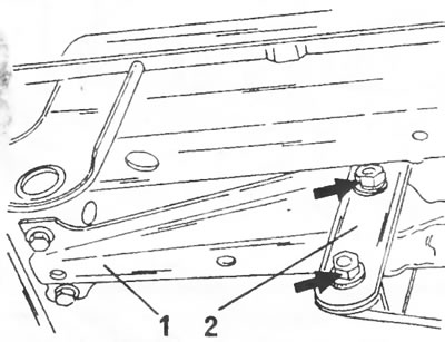
Figure 151. The arrows indicate the nuts for fastening the spring shackle (2), with which it is attached to the spring and console (1).
- Unscrew both spring mounting brackets. To gain access to the console (2), unscrew the bolts (1) from the front. From the rear, that is, from the spring suspension on the cleats, unscrew the four console bolts.
- Lower the rear axle with a jack by a few centimeters, knock out the spring pin from the front side and remove the console.
- Remove the earrings from the rear side of the spring, knock out both pins and remove the console. After knocking out the pins, the spring may fall, take appropriate precautions.
- Pull out the spring.
The rear spring is installed as follows:
- Place the rear console on the spring. To do this, insert the spring U-bolt from the inside, place the U-bolt plate on it and tighten the nuts. Do not tighten bolts and nuts.
- Slide the spring under the frame and attach the rear console with earrings to the frame. In this case, center the console. Figure 152 shows two holes "a" and "b", two rods of a certain diameter are required for centering. Insert a 16 mm diameter rod into hole "a" and a 12 mm diameter rod into hole "b". Once the console is properly seated, tighten the bolts (1) to a torque of 50 Nm.
- Place the free front console, secured to the spring, against the frame and tighten the bolts to a torque of 50 Nm.
- Raise the bridge and insert the spring center bolt into the bridge hole.
- Hammer the springs into the bottom of the U-bolt; if they don't fit into the holes, they can be straightened in a vice so that they fit into the holes easily. Install the nuts with new sheet metal locking washers and tighten the four nuts evenly in a crisscross pattern to a torque of 80 Nm. After tightening the nuts, bend the locking washers.
- Thread the brake hose through the hole in the corner and secure it with a clamp. Screw the union nut of the brake pipe into the hose and tighten it. Avoid twisting the hose.
- Put the wheel on and lower the car.
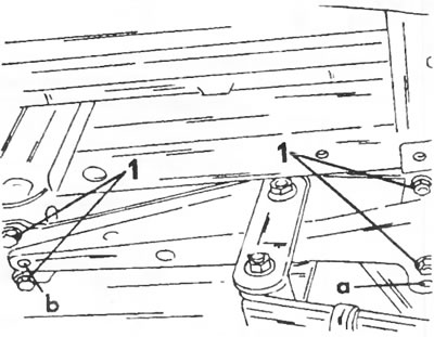
Figure 152. The rear spring console must be centered using two rods before tightening the bolts (1). Holes "a" and "b" have different diameters.
- To tighten the front and rear spring mounts, the rear suspension must be loaded. To do this, place a load in the vehicle so that the dimension "h" in Figure 153 between the adjacent surface of the rubber bump stop (1) and the contact surface "b" on the bridge is 107 mm. Use a tape measure to measure this.
- Tighten the rear leaf spring hanger nuts to 120 Nm and the front leaf spring pin nuts to 150 Nm.
- Unload the car. After installation is complete, the brake system must be bled.
- Tighten the wheel nuts to a torque of 180 Nm.
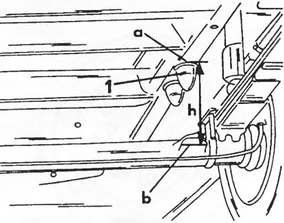
Figure 153.