



Removing the wheel hub is done as follows:
- Loosen the wheel bolts, place the rear of the vehicle on stands and remove the wheels.
- Loosen the wheel guide pin (1) and bolt (2) in Figure 159. Remove the brake drum. Since the drum is firmly seated, it's necessary to screw the bolts into the three holes marked "a." Tighten the bolts evenly in a circular pattern until the brake drum disengages from the wheel hub.
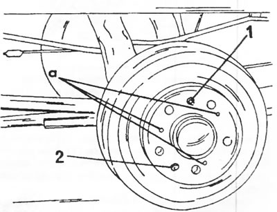
Figure 159. To remove the brake drum, unscrew the guide pin (1) and bolt (2) and screw three bolts into the threaded holes "a".
- Carefully knock off the hub cap with a small chisel. However, it can be easily damaged.
- Locate and remove the wheel bearing nut lock (in two places). The nut can have either left-hand or right-hand threads. On the right wheel, the nut has a right-hand thread and is marked with one hole on the side. The nut on the left wheel has a left-hand thread. Unscrew the nut and remove the spacer washer. Remove the wheel hub together with the wheel bearing. Figure 160 shows the rear axle after this work operation.
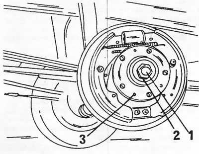
Figure 160. Wheel hub 1. Hub nut; 2. Acceleration washer; 3. Wheel hub
- If it is necessary to remove the axle butt, it is necessary to unscrew the bolts (2) in Figure 161. Depending on their diameter, they are locked or not locked. After this, the axle butt (1) is removed. When purchasing a new butt, please specify the vehicle's chassis number, as the bolt diameter may be 12 or 14 mm.
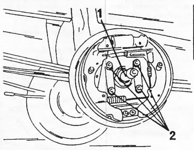
Figure 161. Rear axle with brake drum removed. The axle butt (1) is secured with bolts (2).
- Remove the wheel bearing from the inside of the wheel hub and knock the outer bearing ring out of the hub.
- Knock out the seal from the outside of the wheel hub, remove the bearing and knock out the outer bearing ring from the hub.
- Clean all parts thoroughly and check for reinstallation. Replace damaged parts.
Assembly and installation of the wheel hub is carried out as follows:
- Fill the hub with heat-resistant grease.
- Press the outer bearing rings into the hub from opposite sides. To do this, use rods of appropriate diameters.
- Insert the inner wheel bearing and press the new seal into place along the edge.
- If the axle butt was removed, install it with or without locking bolts. The bolts must be replaced. Bolts with a diameter of 12 mm are installed with a locking device and tightened with a torque of 100 Nm, bolts with a diameter of 14 mm are installed without a locking device and tightened with a torque of 170 Nm.
- Place the wheel hub on the butt and tap it well. Insert the outer, well-lubricated bearing and put on the spacer washer. Screw on the new wheel hub nut without tightening it.
- Place the brake drum on and secure it by tightening the guide pin and bolt.
- After this, the bearing play should be adjusted. The wheel hub and brake drum assembly should have axial play between 0.025 and 0.10 mm. The following description applies to work performed using a special adjustment template. If a template is not available, the bearing nut should be adjusted to provide the required clearance. The backlash is accurately determined using a dial indicator. Note: The right butt has a left-hand thread. This means that the adjustment is not the same on both sides.
- Tighten the wheel bearing nuts to a torque of 20 Nm, turning the brake drum in both directions to seat the bearings.
- Loosen the bearing nut completely and tighten it again to a torque of 70 Nm.
- Place the adjustment template with its hexagon on the nut and secure the upper part of the template with the wheel bolt, as shown in Figure 162.
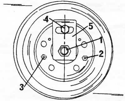
Figure 162. Installing the adjustment template for adjusting wheel bearings. 1. Wheel bearing nut; 2. Wheel guide pin; 3. Brake drum bolt; 4. Wheel bolt; 5. Adjustment template
The right-hand thread side is adjusted as follows:
- While holding the adjustment template, take hold of the bolt (4) in Figure 162 and move it all the way to the left, as shown in Figure 163. Tighten the handbrake.
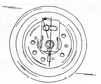
Figure 163. While holding the adjustment template in a vertical position, move the inserted wheel bolt in the direction of the arrow to tighten the nut if the butt has a right-hand thread. On the other wheel, the bolt is moved in the opposite direction.
- After this, loosen the hub nut by moving the template to the left until the bolt rests against the edge of the slot. The rotation angle is shown in Figure 164. In this position, tighten the bolt (4) in Figure 162 to a torque of 10 Nm. If an adjustment template is not available, it is necessary to determine how much to loosen the nut.
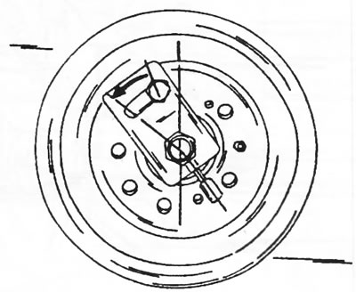
Figure 164. Loosen the nut by moving the template in the direction of the arrow. The working operation for a butt with a right-hand thread is presented. On the other wheel the template moves in the opposite direction.
- Lock the lug of the nut with a blunt rod (see Figure 165). If the work was carried out without a template, check the axial play by moving the brake drum along the axis in both directions. To do this, place the dial indicator on the appropriate stand and attach the measuring probe to the end of the butt. If the play is between 0.025 and 0.10 mm, the nut can be locked. Release the handbrake.
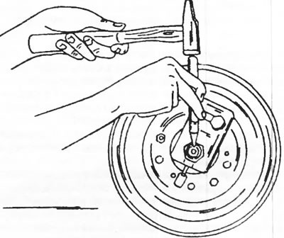
Figure 165. Lock the hub nut in the manner shown. The figure shows the adjustment template.
The left-hand thread side is adjusted as follows:
- Taking hold of the bolt (4) in Figure 162, turn the brake drum to the right, that is, the bolt should not be in the position shown in Figure 163, but on the other side. Apply the handbrake.
- Loosen the nut by moving the template, moving it from the vertical position in the direction opposite to that shown in Figure 164.
- Lock the wheel bearing nuts on both sides (Figure 165). If there is no adjustment template, the instructions given above apply.
- Remove the adjustment template and release the handbrake.
- Carefully hammer in the hub housing.
- Install the wheel and tighten the wheel bolts.