
English Русский
Български
Беларускі
Український
Српски
Hrvatski
Română
Polski
Slovenský
Magyar
Bookmark Articles Sitemap Contacts
Company Hyundai Company Opel Company Skoda Company Kia Company Mitsubishi Company LADA Company Audi
PeugeotBook.ru


Series 100   Series 200   Series 300   400-500   Series 600   Crossovers   Others
 
Partner I (1996-2008) Peugeot 807 (2002-2014) Peugeot 806 (1994-2002) Peugeot J5 (1981-1993)

Double-leaf rear door handle and lock components — removal and installation (Peugeot Partner I)

  • Main
  • Пежо
  • Partner I (1996-2008)
  • Body and interior
  • Doors, locks and windows
  • Double-leaf rear door handle and lock components — removal and installation
0
Table of contents: External door handle 🠇 Lock cylinder 🠇 Door lock 🠇 Upper and lower door latches 🠇 Door latch striker 🠇

External door handle


Note: The outside handle is attached to the door with rivets. For installation, prepare new rivets of the appropriate size.


Removal


1. Remove the inner door trim panel as described in paragraph 11.

2. Remove the plastic cover from the end of the door and disconnect the door handle drive rod from the door lock lever (figure 14.2, a, b).
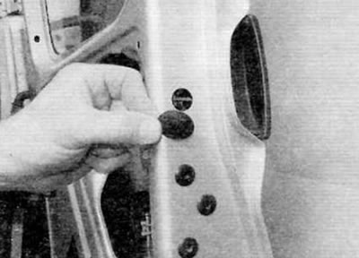
Figure 14.2, a. Remove the plastic cover on the edge of the door...
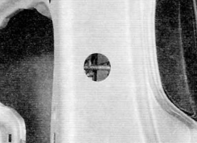
Figure 14.2, a. Remove the plastic cover on the edge of the door...


Figure 14.2, b....and disconnect the door handle rod from the door lock lever

Figure 14.2, b....and disconnect the door handle rod from the door lock lever


3. Using a 6.0mm drill bit, drill out the rivet heads from the outside and remove the handle from the door.


Installation


4. Installation is carried out in the reverse order of removal. Before installing the interior trim panel, check the operation of the handle mechanism. If necessary, adjust the position of the drive rod relative to the door lock lever. Finally, install the interior trim panel as described in paragraph 11.

Lock cylinder


Removal


5. Remove the inner door trim panel as described in paragraph 11.

6. In the door cavity, disconnect the lock cylinder rod from the door lock electric motor (figure 14.6).
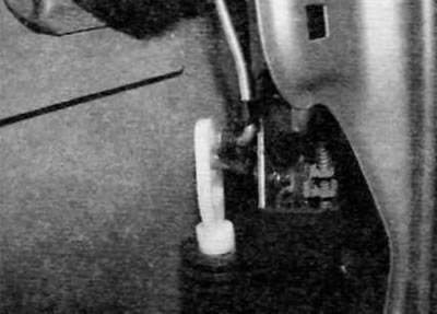
Figure 14.6. Disconnect the lock cylinder rod from the door lock motor

Figure 14.6. Disconnect the lock cylinder rod from the door lock motor


7. Using pliers, remove the large horseshoe clamp from the back of the lock cylinder (figure 14.7).
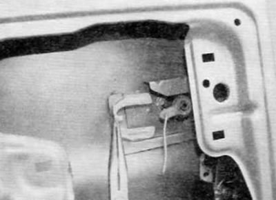
Figure 14.7. Remove the larger horseshoe clamp from the back of the lock cylinder

Figure 14.7. Remove the larger horseshoe clamp from the back of the lock cylinder


8. Remove the lock cylinder and rod from the outside of the door (figure 14.8).
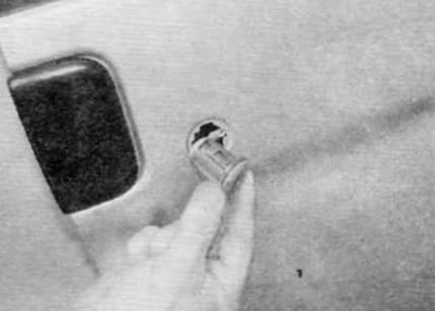
Figure 14.8. Remove the lock cylinder and rod from the outside of the door

Figure 14.8. Remove the lock cylinder and rod from the outside of the door


Installation


9. Installation is carried out in the reverse order of removal. Finally, install the interior door trim panel as described in paragraph 11.

Door lock


Removal


10. Remove the inner door trim panel as described in paragraph 11.

11. Disconnect the electrical connector of the door lock motor (figure 14.11).
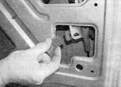
Figure 14.11. Disconnect the door lock motor electrical connector

Figure 14.11. Disconnect the door lock motor electrical connector


12. Remove the four bolts securing the lock to the door (figure 14.12).
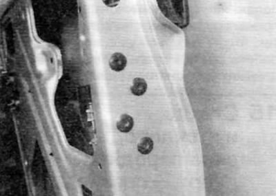
Figure 14.12. Remove the four bolts securing the lock assembly to the door

Figure 14.12. Remove the four bolts securing the lock assembly to the door


13. Remove the lock and the separator plate (figure 14.13).
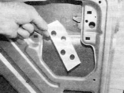
Figure 14.13. Remove the lock and divider plate

Figure 14.13. Remove the lock and divider plate


14. Disconnect the lock cylinder rod from the door lock lever.

15. Mark the installation position of the threaded ends of the upper and lower door latch drive cables. Disconnect the cables from the door lock levers and remove the lock assembly from the door (figure 14.15. a, b).
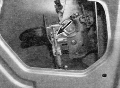
Figure 14.15, a. Mark the installation position of the threaded tips (marked with arrows) drive…

Figure 14.15, a. Mark the installation position of the threaded tips (marked with arrows) drive cables of latches...
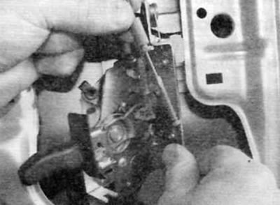

Figure 14.15, b....then disconnect the cables from the door lock levers

Figure 14.15, b....then disconnect the cables from the door lock levers


Installation


16. Installation is carried out in the reverse order of removal. Before installing the interior trim panel, check the operation and synchronization of the upper and lower door latches. If necessary, adjust the position of the ends of the drive cables on the door lock levers. Finally, install the interior trim panel as described in paragraph 11.

Upper and lower door latches


Removal


17. Remove the door lock as described above.

18. Carefully remove the plastic trim panel from the door latch (figure 14.18).
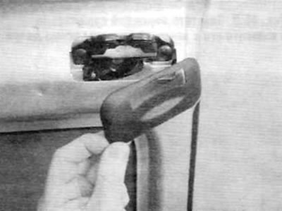
Figure 14.18. Carefully remove the plastic trim panel from the door latch

Figure 14.18. Carefully remove the plastic trim panel from the door latch


19. Remove the two latch mounting screws and remove the latch and drive cable from the door (figure 14.19).
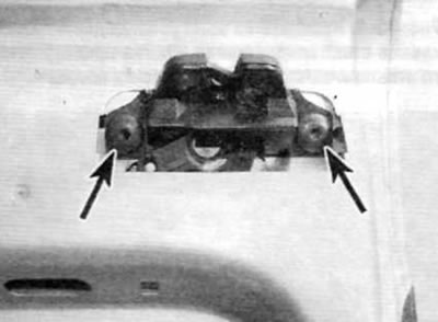
Figure 14.19. Remove the two screws securing the door latch

Figure 14.19. Remove the two screws securing the door latch


Installation


20. Installation is performed in the reverse order of removal.

Door latch striker


Removal


21. When working with the lower latch striker, bend back the floor covering to gain access to the striker cover. Remove the three screws and lift the latch housing cover off the floor.

22. When working with the mating part of the upper latch, remove the protective rubber cover (figure 14.22).
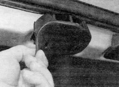
Figure 14.22. Remove the protective rubber cover from the mating part of the upper latch

Figure 14.22. Remove the protective rubber cover from the mating part of the upper latch


23. Mark the position of the mating part on the body to ensure correct installation. Remove the two bolts and the corresponding latch part from the body (figure 14.23).
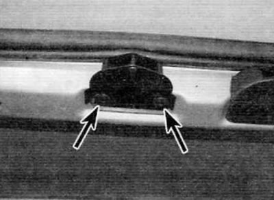
Figure 14.23. Bolts for fastening the mating part of the latch (marked with arrows)

Figure 14.23. Bolts for fastening the mating part of the latch (marked with arrows)


Installation


24. Installation is carried out in the reverse order of removal. Before tightening the bolts, the position of the latch's mating part should be adjusted (using elongated bolt holes) so as to achieve satisfactory operation of the lock. Use the marks made before removal (if applicable).
This article is available at russian, bulgarian, belarusian, ukrainian, serbian, croatian, romanian, polish, slovak, hungarian
Article reviewed by editor: Nikonova Veronica
Share information:
Previous
Partner I: Doors, locks and windows
Next

Sliding Door Handle and Lock Components — removal and…
Front Door Handle and Lock Components — removal and installation
Interior Door Trim Panels — removal and installation
Doors — removal and installation
Front door window glass and window regulator — removal and…
Liftgate and support pillars — removal and installation
Liftgate Lock Components — removal and installation
Elements of the central locking system — removal and installation
Windscreen, glass for the liftgate and glass for the rear double…
See similar information for other Peugeot models

➨ Doorhandle and lock components — removal and refitting Peugeot 106 (1991-2003)
➨ Disassembly and assembly of the rear bumper (3- and 5-door… Peugeot 207 (2006-2014)
➨ Replacing the rear door lock Peugeot 307 (2001-2008)
➨ Rear door lock (Combi models) — removal and installation Peugeot 405 (1987-1997)
➨ Rear Crankshaft Oil Seal (Flywheel Side) — Replacement Peugeot 605 (1989-2000)
Link to this article in different formats
Comments and feedback from visitors
Виктор
(01.03.2025 11:13)
Спасибо, всё понятно, без лишней воды!
answer quote


Add two numbers 46 + 30


Partner I (1996-2008) 
  • General information
  • Introduction to the guide
  • Faults en route
  • Weekly checks
  • User manual
  • Maintenance (petrol)
  • Maintenance (diesel)
  • Power unit
  • Petrol engines
  • Diesel engines «XUD»
  • Diesel engines «DW»
  • Overhaul of petrol engines
  • Overhaul of diesel engines
  • Cooling and heating
  • Power and exhaust (petrol)
  • Power and exhaust (XUD diesels)
  • Power and exhaust (DW diesels)
  • Emission reduction
  • Starting and charging system
  • Transmission
  • Clutch
  • Mechanical gearbox
  • Drive shafts
  • Chassis, running gear
  • Brake system
  • Car suspension
  • Steering
  • Body and interior
  • Exterior (external elements)
  • Interior (internal elements)
  • Doors, locks and windows
  • Electrical equipment
  • Equipment and devices
  • Electrical circuits
Peugeot 807 (2002-2014) 
  • General information
  • Operating instructions
  • Maintenance
  • Troubleshooting
  • Power unit
  • Gasoline engines
  • Diesel engines
  • Cooling and heating
  • Fuel injection (petrol)
  • Fuel system (diesel)
  • Fuel system
  • Exhaust system
  • Ignition system
  • Transmission
  • Clutch
  • Manual gearbox
  • Automatic gearbox
  • Chassis, running gear
  • Brake system
  • Car suspension
  • Steering system
  • Body and interior
  • Exterior (external elements)
  • Interior (internal elements)
  • Electrical equipment
  • Power devices
  • Electrical circuits
Peugeot 806 (1994-2002) 
  • General information
  • User manual
  • Maintenance
  • Power unit
  • Petrol engines
  • Diesel engines
  • Lubrication system
  • Cooling system
  • Fuel injection (petrol)
  • Fuel system (diesel)
  • Ignition and exhaust systems
  • ECM Bosch Motronic MP 3.2
  • ECM Magneti-Marelli (MM)
  • Transmission
  • Clutch
  • Mechanical gearbox
  • Chassis, running gear
  • Brake system
  • Car suspension
  • Steering
  • Electrical equipment
  • Equipment and devices
  • Electrical circuits
Peugeot J5 (1981-1993) 
  • General information
  • Introduction to manual
  • Specifications
  • Gasoline engine
  • Engine repair
  • Lubrication system
  • Cooling system
  • Fuel system
  • Ignition system
  • Diesel engine
  • Engine repair (DB9)
  • Lubrication system (DB9)
  • Cooling system (DB9)
  • Fuel injection (DB9)
  • Engine repair (U25)
  • Lubrication system (U25)
  • Cooling system (U25)
  • Fuel injection (U25)
  • Transmission
  • Clutch
  • Gearbox
  • Drive shafts
  • Chassis, running gear
  • Steering system
  • Car suspension
  • Brake system
  • Electrical equipment
  • Power devices
  • Electrical circuits
PeugeotBook.ru © 2018–2026 | Mobile version | Sitemap: EN BG BY UA RS HR RO PL SK HU | Write message | Site search | Add to bookmarks | Peugeot owners
106 (1991-2003) | 206 (1998-2012) | 207 (2006-2014) | 305 (1977-1989) | 306 (1993-2002) | 307 (2001-2008) | 405 (1987-1997) | 406 (1995-2004) | 605 (1989-2000) | Partner-I (1996-2008) | Eurovans-807 (2002-2014) | Eurovans-806 (1994-2002) | J5 (1981-1993) |
Cookies are used to ensure the correct display of pages on the site.