



Table of contents: ECU Block 🠇 Crankshaft speed and position sensor 🠇 Coolant temperature sensor 🠇 Incoming air temperature sensor 🠇 Accelerator pedal position sensor 🠇 Intake Manifold Pressure Sensor 🠇 Injector needle lift sensor 🠇 Vehicle speed sensor 🠇 Preheating system control unit 🠇 EGR valve 🠇
ECU Block
The ECU is the main unit of the engine management system. It controls the fuel injection system and emission control systems.
The ECU receives signals from sensors that monitor changing engine operating conditions such as intake air temperature, coolant temperature, engine speed, accelerator pedal position, etc. These signals are used by the ECU to determine the optimal amount of fuel to deliver to the fuel pump.
Removal
Before removing any fuel system component, disconnect the negative battery terminal.
1. Remove the ECU cover.
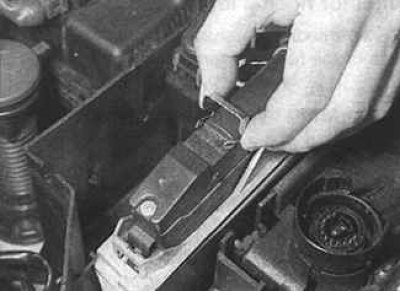
2. Disconnect the electrical connector by first lifting the locking lever at the top of the connector.
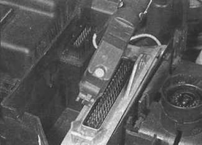
3. Remove the connector from the back, disconnect the front and remove the ECU from the pins.
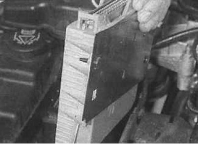
4. Lift the ECU unit up and remove it from the box.
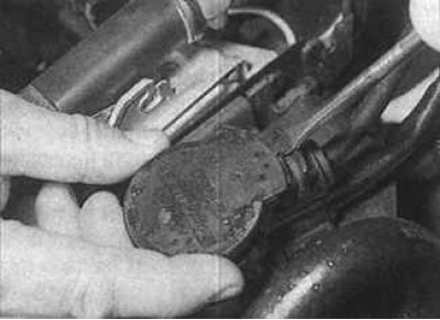
5. Turn the fuel pump wiring connector on the top of the box clockwise.
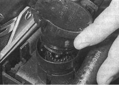
6. Unhook the mounting tab using a screwdriver, then turn the connector counterclockwise and lift up.
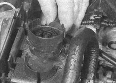
7. Remove the two screws securing the wiring connector base to the block box and lift the connector base up.
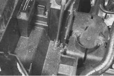
8. Unscrew the inner and outer mounting bolts.
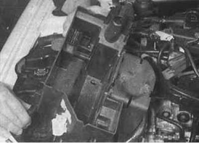
9. Remove the block box.
Installation
Installation is carried out in the reverse order of removal.
Crankshaft speed and position sensor
This is an inductive pulse generator, bolted to the clutch housing and creating pulses when the bridges between the holes in the flywheel pass near it.
When each jumper passes near the sensor, one pulse is generated, by which the ECU unit determines the crankshaft rotation frequency. One of the jumpers between the two holes is missing, and by missing one signal the ECU unit determines the position of the crankshaft.
Removal
1. Trace the wiring from the sensor to the wiring connector and disconnect it from the main harness.
2. Remove the rubber sealing ring, unscrew the bolts and remove the sensor from the crankcase.
Installation
Installation is carried out in the reverse order of removal.
Coolant temperature sensor
The coolant temperature sensor is a negative temperature coefficient thermistor, meaning that as the sensor temperature increases, its resistance decreases.
Incoming air temperature sensor
The inlet air temperature sensor is a negative temperature coefficient thermistor, meaning that as the sensor temperature increases, its resistance decreases. This is also used to adjust the amount of fuel supplied.
Removal
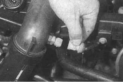
Disconnect the electrical connector from the sensor and unscrew the sensor from the intake manifold at the front of the engine.
Installation
Installation is carried out in the reverse order of removal.
Accelerator pedal position sensor
The accelerator pedal position information is transmitted to the ECU by this sensor. The accelerator cable is connected to the pedal position sensor, which converts the pedal movement into an electrical signal. After processing this signal and using the information received from other sensors, the ECU electronically controls the high-pressure fuel pump so that the optimum amount of fuel is supplied to achieve the desired vehicle dynamics.
Removal
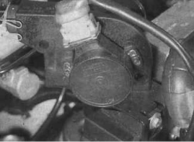
1. Remove the accelerator cable from the lever on the accelerator pedal position sensor located on the left front side of the engine compartment.
2. Remove the accelerator cable housing from the sealing ring in the sensor hanger.
3. Disconnect the electrical connector, unscrew the mounting bolts and remove the sensor with its hanger. If it is necessary to remove the sensor from the installation hanger, mark the position of the sensor relative to the hanger, then unscrew the two screws and remove the sensor.
Installation
Installation is carried out in the reverse order of removal.
Intake Manifold Pressure Sensor
The pressure sensor measures the vacuum in the intake manifold and transmits information to the ECU to calculate engine load at any accelerator pedal position.
The sensor may be mounted at the bottom of the air cleaner or in other locations in the front left side of the engine compartment.
Removal
1. Remove the vacuum hose and electrical connector and unscrew the two sensor mounting bolts.
2. Remove the sensor from its socket.
Installation
Installation is carried out in the reverse order of removal.
Injector needle lift sensor
The injector needle lift sensor is an integral part of one of the fuel injectors, which sends a signal to the ECU when the injector opens.
Vehicle speed sensor
The vehicle speed sensor consists of a converter included in the speedometer drive. The ECU uses the sensor signals to change the amount of fuel supplied in accordance with the vehicle speed.
Preheating system control unit
This is an ECU controlled relay that connects the glow plugs of the pre-heating system to the ECU for a specified time when starting a cold engine.
EGR valve
The return of a portion of the exhaust gases to the intake manifold is controlled by the ECU in combination with the electromagnetic valve and the EGR valve. The vacuum from the vacuum pump is directed to the EGR valve through the electromagnetic valve according to the engine speed, load and altitude.
Examination
1. If a fault occurs in the system, check that all electrical connectors are connected and not oxidized. Check that the air filter element is clean, the compression pressure in the engine cylinders is within normal limits and the engine ventilation hoses are not damaged.
2. If everything looks fine on the outside, but there is a fault in the system, you need to check the fuel system at a Peugeot station.