
2. Lubricate cylinders, pistons and piston rings.
3. Piston installation must begin with the first cylinder. Check the correct position of the piston rings on the piston, then compress them with a special mandrel.
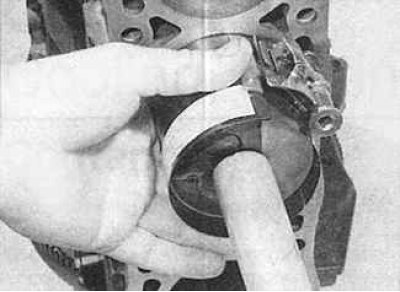
4. Insert the piston with the mandrel that compresses the rings into the top of the first cylinder. On petrol engines, check that the arrow on the piston head points towards the timing belt, and on diesel engines, the notch on the piston head points towards the front of the cylinder block. Using a wooden block (hammer handle) press the piston and press it together with the piston into the cylinder.
5. Check the alignment of the lower head of the connecting rod with the crankshaft journal, if necessary tighten the piston with the connecting rod and install the lower head of the connecting rod with the insert on the crankshaft journal.
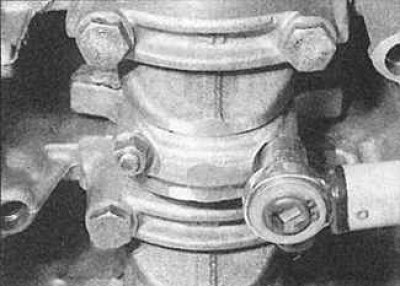
6. Establish a cover of the lower head of a rod with an insert and tighten nuts the demanded moment. Please note that the previously applied markings on the connecting rod cap and connecting rod must be aligned.
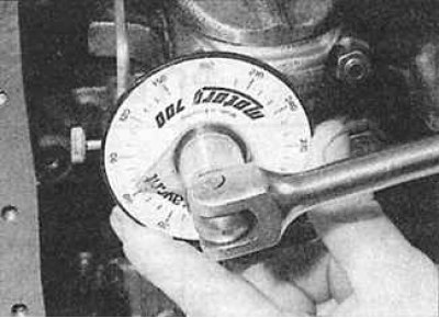
7. Tighten the connecting rod cap nuts with a torque wrench.
8. Tighten the connecting rod cap nuts to the required angle.
9. Turn the crankshaft after tightening the bearing cap nuts. The crankshaft must rotate freely. Some force will be required when installing new liners, but at the same time there should be no binding or turning the shaft with great effort.
10. Install the remaining three pistons in the same manner.
11. Install the cylinder head and oil pump.
Bearing shell selection
Most engines use two sizes of connecting rod bearings: a standard size for use with a standard crankshaft and an oversized size for use with a crankshaft that has been ground once.
Before installing the connecting rod head, check the operating clearance of the connecting rod bearing.
Checking the operating clearance of the connecting rod bearing shell
1. Clean the connecting rod bearings and their sockets. The working clearance can be checked in two ways.
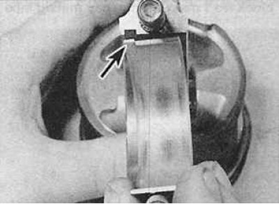
2. One of the methods (which assumes the presence of a micrometer to measure the diameter of the holes) consists in installing the connecting rod bearing caps together with the bushing on the connecting rod and screwing them to the required torque. When installing the bearing into the connecting rod, the protrusion on the bearing (arrow) should fit into the groove on the connecting rod.
3. Measure the inside diameter of each assembled pair of bearing shells. Measure the diameter of each connecting rod journal of the crankshaft. Subtract the corresponding diameter of the crankshaft journal from the measured bearing diameter.
4. Second (and more accurate method) is to use a product known as Plastigage. This is a round plastic rod that is compressed between the liner and the crankshaft journal. After removing the connecting rod bearing cap, the deformed plastic rod is measured with a special gauge, which is included in the Plastigage kit. The procedure for using Plastigage is as follows.
5. Install the connecting rod with bushing on the appropriate crankshaft journal. The crankshaft journals and bearings must be completely clean and dry.
6. Cut off a piece of plastic Plastigage rod (it should be slightly shorter than the width of the connecting rod bearings) and install it on the crankshaft journal to be measured.
7. Install the connecting rod caps with the lower bearings and tighten the mounting bolts to the specified torque. Do not rotate the crankshaft while measuring the clearance using the Plastigage method.
8. Unscrew the connecting rod cover of the liner, remove it and attach the scale ruler printed on the package to the deformed plastic rod. By comparing the width of the deformed plastic rod with the reference width on the scale bar, determine the amount of gap.
9. Finally, thoroughly clean any traces of Plastigage material from the liners and crankshaft.