
English Русский
Български
Беларускі
Український
Српски
Hrvatski
Română
Polski
Slovenský
Magyar
Bookmark Articles Sitemap Contacts
Company Hyundai Company Opel Company Skoda Company Kia Company Mitsubishi Company LADA Company Audi
PeugeotBook.ru


Series 100   Series 200   Series 300   400-500   Series 600   Crossovers   Others
 
Peugeot 405 (1987-1997) Peugeot 406 (1995-2004)

Removal and installation of the BE3 gearbox (Peugeot 406)

  • Main
  • 40X
  • Peugeot 406 (1995-2004)
  • Transmission
  • Mechanical gearbox
  • Removal and installation of the BE3 gearbox
0
Table of contents: Removal 🠇 Installation 🠇

Removal


1. Disconnect the negative battery terminal.

2. Raise the front of the car and secure it on stands. Remove the front wheels and remove the fender guard. Remove the splash guard from under the engine.

3. Drain the gearbox oil and replace the oil filler and drain plugs.

4. Remove both drive shafts.
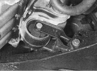
5. From under the car, unscrew the bolts securing the support to the intermediate bearing housing…


5. From under the car, unscrew the bolts securing the support to the intermediate bearing housing of the drive shaft and the lower frame. Move the support to the side.

6. Remove the air filter housing and intake pipe system.

7. Remove the accelerator cable from the throttle body or high pressure fuel pump.

8. Remove the electrical wiring from the transmission along with the reverse light switch, speedometer drive sensor and ground bus.

9. Remove the brake pad wear indicator lamp and ABS system wiring harness from the brackets and move it to the side.

10. Using a screwdriver blade as a lever, disconnect the three selector rods from their corresponding ball joints on the transmission.

11. Remove the cable, suspension and RPM/TDC sensor.

12. Move the air conditioning pipe and power steering gear to the side.


13. Remove the clutch release cable from the transmission.

14. Unscrew the starter mounting bolts and move the starter to the side without disconnecting the wires from it.

15. Unscrew the bolt and remove the clutch cable hanger.

16. On the speedometer cable drive, remove the pin and remove the cable from the speedometer drive sensor. If present, disconnect the electrical connector. Unscrew the bolt and remove the speedometer drive sensor together with the heat shield. Unscrew the three mounting bolts and remove the speedometer drive sensor housing together with the circular section gasket from the gearbox housing.

17. Using a winch, raise the left side of the power unit so that the weight of the power unit is supported only by the winch.

18. Place a jack under the transmission and raise it enough so that the weight of the transmission is supported by the jack.
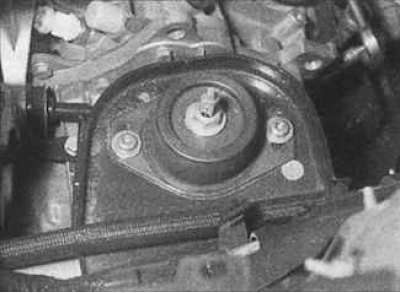
19. Unscrew the central nut of the left support of the power unit suspension. Unscrew the two bolts…


19. Unscrew the central nut of the left support of the power unit suspension. Unscrew the two bolts and remove the rubber cushion from the suspension of the unit.
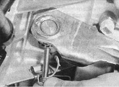
20. On models with a «pull» type clutch release mechanism, remove the pin or unscrew the mounting…


20. On models with a "pull" type clutch release mechanism, remove the pin or unscrew the mounting bolt.
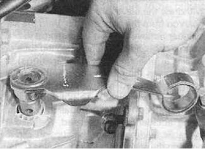


21. Remove the clutch release lever from the top of the release shaft. Disconnect the release…


21. Remove the clutch release lever from the top of the release shaft. Disconnect the release bearing from the release fork.
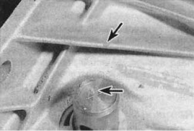
22. Place marks through the center of the clutch release fork shaft and mark the position of the…


22. Place marks through the center of the clutch release fork shaft and mark the position of the shaft relative to the gearbox housing (the marks are indicated by arrows).

23. Unscrew the bolts and remove the lower flywheel protective plate.

24. Remove the gearbox mounting bolt from the rear of the cylinder block.

25. Supporting the gearbox with a jack, unscrew the remaining bolts securing the gearbox to the engine.

26. Lower the powertrain and jack up the gearbox away from the engine. Lower the gearbox under the vehicle.

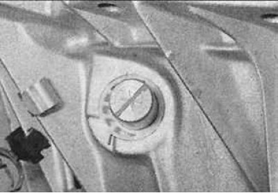
27. Make a second mark to indicate the position of the clutch release shaft relative to the transmission housing after the transmission has been removed, noting the angle through which the clutch release fork has rotated.


Aligning the second mark on the clutch release shaft with the mark on the gearbox before installing the gearbox in place


Installation


Installation


Installation is carried out in the reverse order of removal, taking into account the following points:
  • replace the drive shaft sealing rings;
  • check that the guide pins are in place;
  • align the mark on the clutch release shaft with the second mark on the gearbox housing made when removing the gearbox. Lubricate the threads of the left suspension mounting bolt with a bolt-loss preventer;
  • tighten all bolts and nuts to the specified torque;
  • install drive shafts;
  • remove oil from gearbox.
This article is available at russian, bulgarian, belarusian, ukrainian, serbian, croatian, romanian, polish, slovak, hungarian
Article reviewed by editor: Vinogradov Robert
Share information:
Previous
Peugeot 406: Mechanical gearbox
Next

Speedometer Drive Sensor — Removal and Installation
Reverse Light Switch — Removal, Checking and Installation
Replacing sealing rings
Cable shift drive (ML5T gearbox)
Gear shift control (BE3 gearbox)
Manual transmission ML5T
Main faults of a manual gearbox
See similar information for other Peugeot models

➨ Gearbox BE4/5 Peugeot 207 (2006-2014)
➨ Engine and gearbox — removal Peugeot 305 (1977-1989)
➨ Checking the transmission fluid level in the gearbox Peugeot 605 (1989-2000)
➨ Checking the transmission fluid level in the gearbox Peugeot 806 (1994-2002)
Link to this article in different formats
Comments and feedback from visitors
No comments yet


Add two numbers 38 + 23


Peugeot 406 (1995-2004) 
  • General information
  • User manual
  • Maintenance (gasoline)
  • Maintenance (diesel)
  • Power unit
  • Gasoline engines
  • Diesel engines
  • Engine overhaul
  • Cooling and heating
  • Fuel system (gasoline)
  • Fuel system (diesel)
  • Engine electrical equipment
  • Transmission
  • Clutch and drive shafts
  • Mechanical gearbox
  • Automatic gearbox
  • Chassis, running gear
  • Brake system
  • Car suspension
  • Steering
  • Body and interior
  • Exterior (external elements)
  • Interior (internal elements)
  • Doors, locks and windows
  • Electrical equipment
  • Equipment and devices
  • Electrical circuits
Peugeot 405 (1987-1997) 
  • General information
  • User manual
  • Maintenance
  • Power unit
  • Petrol engines 1.4 l
  • Petrol engines 1.6-2.0 l
  • Diesel engines
  • Ignition system
  • Fuel system (carburetor)
  • Single point fuel injection
  • Multipoint fuel injection
  • Cooling and lubrication system
  • Exhaust system
  • Transmission
  • Clutch
  • Manual gearbox MA
  • Manual gearbox BE
  • Automatic gearbox
  • Drive shafts
  • Chassis, running gear
  • Steering
  • Front suspension
  • Rear suspension
  • Brake system
  • Body and interior
  • Exterior (external elements)
  • Interior (internal elements)
  • Doors, locks and windows
  • Electrical equipment
  • Equipment and devices
  • Electrical circuits
PeugeotBook.ru © 2018–2026 | Mobile version | Sitemap: EN BG BY UA RS HR RO PL SK HU | Write message | Site search | Add to bookmarks | Peugeot owners
106 (1991-2003) | 206 (1998-2012) | 207 (2006-2014) | 305 (1977-1989) | 306 (1993-2002) | 307 (2001-2008) | 405 (1987-1997) | 406 (1995-2004) | 605 (1989-2000) | Partner-I (1996-2008) | Eurovans-807 (2002-2014) | Eurovans-806 (1994-2002) | J5 (1981-1993) |
Cookies are used to ensure the correct display of pages on the site.