
- tools for removing ball bearings - 0216G1, 0217G2;
- clamp for clamps.
Removing the gearbox control mechanism is carried out in the following order:
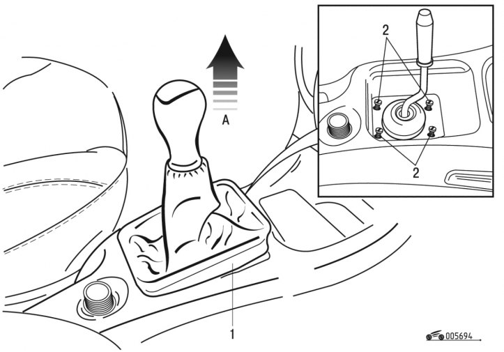
Pic. 6.94. Corrugated pouch with handle: 1 - corrugated cover; 2 - bolts
- remove the handle and bellows 1 (pic. 6.94) from the center console;
- unscrew bolts 2;
- remove clamp 1 (see fig. 6.6) with the aid of a device;
- remove tube 2 crankcase ventilation;
- remove the air filter 4 and sleeve 3;
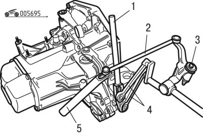
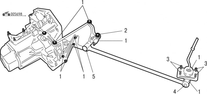
Pic. 6.95. Gearbox control mechanism: 1, 5 - fixtures; 2, 4 - thrust; 3 - bolt
- remove rod 4 (pic. 6.95) using tool 1;
- remove draft 2 by means of adaptation 5;
- unscrew bolt 3;
- raise the car on a lift;
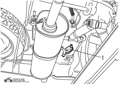
Pic. 6.96. Exhaust hanger: 1 - collar
- remove clamp 1 (pic. 6.96) exhaust pipe hangers, as well as other clamps;
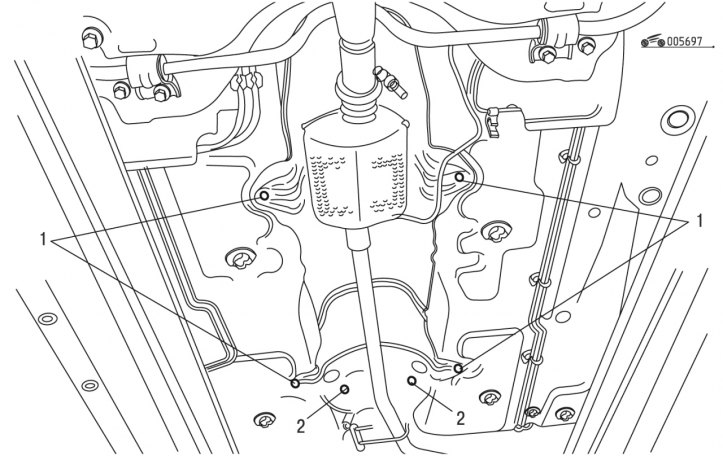
Pic. 6.97. Mounting the control mechanism: 1 - nuts; 2 - bolts
- unscrew bolts 2 (pic. 6.97) and nuts 1 for fastening the mechanism;
- remove the gearbox control mechanism.
Install the gearbox control mechanism in the following order:
Pic. 6.98. Installing the gearbox control mechanism: 1, 5 - elastic hinges; 2 - bolt; 3 - bolts; 4 - nut
- put ESSO NORVA 275 grease into the elastic joints 1 (pic. 6.98);
- put ESSO 3106 grease into elastic joint 5;
- tighten nut 4 to 8 Nm;
- apply LOCTITE FRENETANCH to the threads of bolt 2 and tighten;
- tighten bolts 3 to 8 Nm;
- reinstall the shift knob and bellows.