
- universal puller Facom U53T;
- device for installing the output shaft bearing on the side of the 4th gear - 0317-B, 7.101T-B;
- tool for removing the retaining ring - 0317-P, 4508T-V;
- adapter for removing the intermediate washer - 0317-Q, 4508T-U;
- device for installing the output shaft bearing on the side of the 1st gear gear - 0317-E, 7.101T-E;
- device for installing lock rings of the output shaft 0317-R, 4508-Т.Т.
Disassemble the secondary shaft in the following order:
- dismantle the gearbox as described above and remove the primary, secondary shafts and differential;
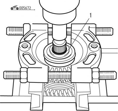
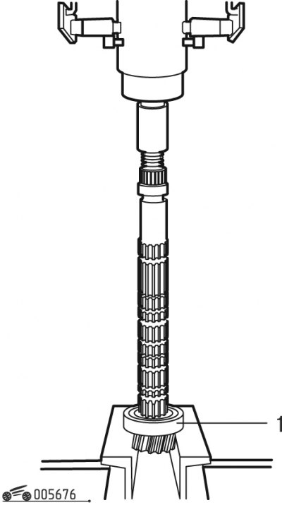
Pic. 6.72. Removing the bearing from the output shaft: 1 - bearing
- press bearing 1 (pic. 6.72) from the secondary shaft using the tool shown in the figure;
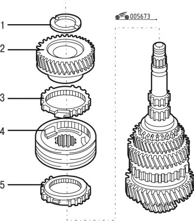
Pic. 6.73. Removing the synchronizer of 3rd and 4th gears: 1 - washer; 2 - driven gear of the 4th gear; 3, 5 - synchronizer rings; 4 - synchronizer of 3rd and 4th gears
- remove washer 1 (pic. 6.73) from the secondary shaft;
- remove the 4th gear;
- remove the synchronizer 4 of the third and fourth gears together with rings 3 and 5;
Attention! It is forbidden to disassemble the synchronizer, as in this case balls and springs may fall out.
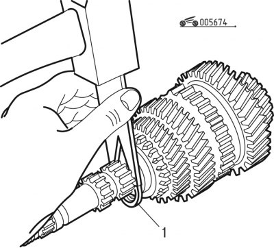
Pic. 6.74. Removing the retaining ring: 1 - retaining ring
- remove retaining ring 1 (pic. 6.74) with the aid of a device;
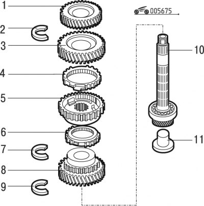
Pic. 6.75. Removing the synchronizer of 1st and 2nd gears with gears: 1 - driven gear of the 3rd gear; 2, 7, 9 - retaining rings; 3 - driven gear of the 2nd gear; 4, 6 - synchronizer rings; 5 - synchronizer of 1st and 2nd gears; 8 - driven gear of the 1st gear; 10 - secondary shaft; 11 - tip for lubrication
- remove driven gear 1 (pic. 6.75) 3rd gear;
- remove the retaining ring 2;
- remove the driven gear 3 of the second gear;
- remove the synchronizer 5 of the first and second gears together with rings 4 and 6;
- remove the retaining ring 7;
- remove the 1st gear driven gear;
- remove the retaining ring 9;
- remove the tip 11 for lubrication;
Attention! It is forbidden to disassemble the synchronizer, as in this case balls and springs may fall out.
Pic. 6.76. Bearing removal: 1 - bearing
- press bearing 1 (pic. 6.76).
Assemble the secondary shaft in the following order:
Attention! Removed bearings must be replaced each time. Check the teeth of the gears mounted on the output shaft and the bearing surfaces of the shaft.
- press in new bearing 1 (see fig. 6.76) on the secondary shaft;
- install a new retaining ring 9 (see figure 6.75) and a new plastic tip 11 for lubrication;
- install driven gear 8;
- install a new retaining ring 7;
- assemble the synchronizer of the 1st and 2nd gears with rings 4 and 6 so that the synchronizer crackers enter the grooves of the rings, then install the synchronizer assembly on the output shaft;
- install driven gear 3 2nd gear;
- install a new retaining ring 2;
- install driven gear 1 3rd gear;
- assemble synchronizer 4 (see fig. 6.73) 3rd and 4th gears with rings 3 and 5 so that the synchronizer crackers enter the grooves of the rings, then install the synchronizer assembly on the output shaft;
- install the driven gear 2 of the 4th gear;
- install washer 1;
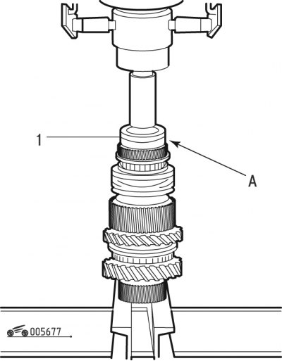
Pic. 6.77. Bearing installation: 1 - bearing
- press in new bearing 1 (pic. 6.77) onto the output shaft with groove A up.
Attention! When pressing the bearing, do not rest against the grease fitting.