



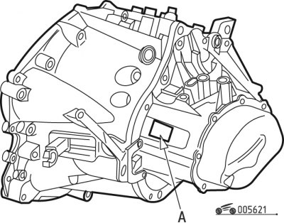
Figure 6.21. Gearbox marking location BE4/5
The gearbox is marked in the area shown in Figure 6.21. The unit marking and factory serial number are indicated.
When removing and installing the gearbox at Peugeot service centers, the following special tool is used:
- ball joint removal tools - 0216G1, 0126G2;
- mandrels for installing axle shaft flange seals — 0317U, 0317T;
- gearbox suspension axle removal tool — 0317 AB;
- cross member for holding the power unit;
- mandrel for centering the driven clutch disc.
[Information copied from the resource: PEUGEOTBOOK]
Remove the gearbox in the following order:
- remove the air filter with air supply pipes;
- remove the battery;
- remove the battery tray;
- remove the left mudguard;
- disconnect, release from fasteners and move aside the wiring harnesses connected to the gearbox;
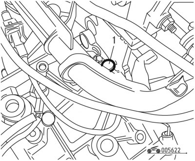
Figure 6.22. Removing the engine crankshaft speed sensor: 1 - sensor
- remove sensor 1 (figure 6.22) engine crankshaft speed;
- unscrew the three bolts securing the starter and move it to the side without disconnecting the wires;
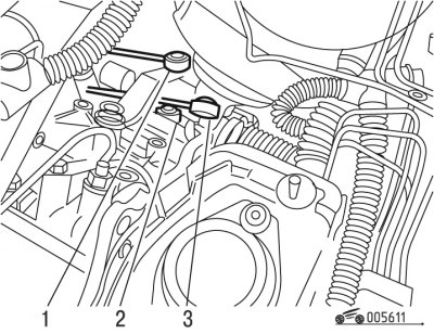
Figure 6.23. Removing the gear shift rods: 1 - gear shift rod; 2 - jet thrust; 3 - leash lever
- disconnect rod 1 (figure 6.23) gear shifting with a device;
- disconnect the drive lever 3 using the device;
- disconnect the jet thrust 2 using the device;
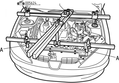
Figure 6.24. Installing the crossbar: A - location of installation of stops
- install the crossbar as shown in Figure 6.24;
Attention! Install the stops in places A (see figure 6.24).
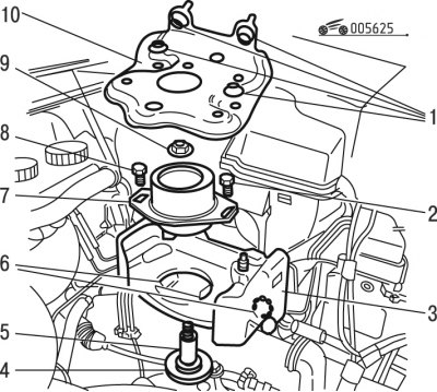
Figure 6.25. Gearbox support: 1, 2, 6, 8 - bolts; 3 - gearbox axle bracket; 4 - gearbox axis; 5 - spacer; 7 - rubber cushion; 9 - nut; 10 - support
- unscrew bolts 1 (figure 6.25) battery support mounts;
- remove support 10 of the battery;
- unscrew nut 9 of the gearbox support axle with washer;
- unscrew the 8 bolts securing the cushion;
- remove the gearbox support rubber cushion;
- unscrew bolts 6;
- remove the 3rd axle bracket of the gearbox support;
- remove spacer 5;
- remove axle 4 of the gearbox support with the washer using a tool;
Cable clutch drive
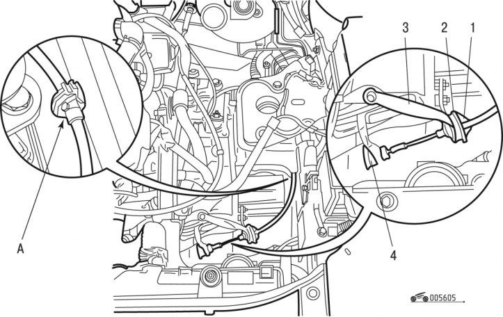
Figure 6.5. Clutch cable drive (gearbox BE4): 1 - cable sheath tip; 2 - bushing; 3 - support; 4 - bushing
- move tip 1 (see figure 6.5) and bushing 2 supports 3 cables;
- remove bushing 4 from clutch release fork;
Clutch hydraulic drive
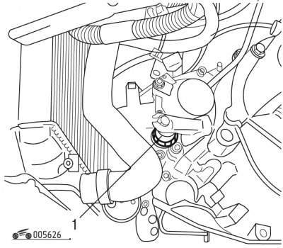
Figure 6.26. Removing the clutch slave cylinder: 1 - working cylinder
- disconnect slave cylinder 1 (figure 6.26) clutch drive from the crankcase without disconnecting from the hose;
All drives
- - remove the front wheels;
- remove the front wheel drive shafts;
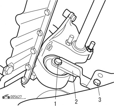
Figure 6.27. Powertrain swing limiter: 1, 3 - bolts; 2 - limiter
- unscrew bolts 1 and 3 (figure 6.27) and remove the powertrain swing limiter;
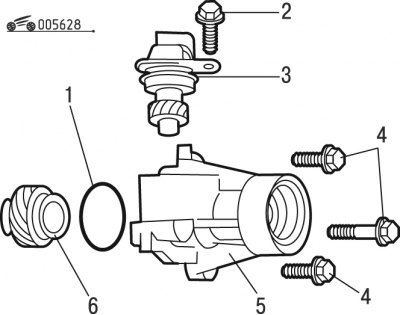
Figure 6.28. Differential extension: 1 - sealing ring; 2, 4 - bolts; 3 - speedometer drive gear support; 5 - differential extension; 6 - speedometer drive gear
- unscrew bolt 2 (figure 6.28) speedometer drive gear supports and remove gear 6 from the crankcase;
- unscrew bolts 4 and remove the differential extension;
- remove sealing ring 1;
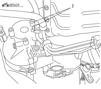
Figure 6.29. Lower gearbox mounting bolts: 1 - bolts
- unscrew the lower bolts 1 (figure 6.29) gearbox mounts;
- lower the power unit slightly using the crossbar (see figure 6.24);
- hook the lifting cables to the gearbox;
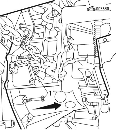
Figure 6.30. Upper gearbox mounting bolts: 1 - bolts
- unscrew the top bolts 1 (figure 6.30) fasten the gearbox housing to the engine and remove the gearbox;
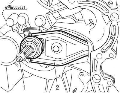
Figure 6.31. Bearing with clutch release fork: 1 - bearing; 2 - clutch release fork
- remove bearing 1 (figure 6.31) clutch release and fork 2.