



- replace with new axle shaft flange seals, extension sleeve, self-locking nuts and lock washers;
- check the technical condition of the fork ball joint insert;
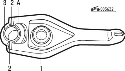
Figure 6.32. Clutch release fork: 1 - clutch release bearing; 2 - protrusions; 3 - fork support; A - lubrication points
- lubricate the ends of the fork in places A with a thin layer of MOLYKOTE BR2 PLUS grease (figure 6.32);
- install the clutch release bearing so that its protrusions 2 enter the fork tips;
- lubricate the clutch release bearing guide bush with a thin layer of MOLYKOTE BR2 PLUS grease;
Caution: Do not lubricate the gearbox input shaft splines.
- install the bearing with the clutch release fork in place;
- move the bearing on the sleeve several times;
Caution: Make sure the pins are present to install the gearbox. Be careful not to pinch the wiring harnesses when installing the gearbox.
- fill the space between the edges of the seals with grease;
- connect the gearbox to the engine;
- reinstall the top bolts 1 (see figure 6.30) and tighten them to a torque of 55 Nm;
- clean the threads of the axis 4 (see figure 6.25) and lubricate it;
- install the axle with the washer in place;
- tighten the axle to 50 Nm;
- install spacer 5;
- install bracket 3;
- tighten bolts 6 to 60 Nm;
- install rubber cushion 7 of gearbox support;
- "tighten" nut 9 and bolts 8 of the cushion;
- center the position of the power unit before final tightening of the support cushion fastening elements;
- tighten bolts 8 to 30 Nm and nut 9 to 65 Nm;
- install support 10 of the battery and tighten bolts 1 to a torque of 20 N·m;
Cable clutch drive
- install bushing 4 (see figure 6.5) on the clutch release fork;
- lubricate the flange of the bushing 2 and the cylindrical end of the tip 1 of the cable sheath with consistent grease;
- insert bushing 2 into support 3 of the cable and then tip 1 of the sheath into the bushing;
- install the coupling into the retainer at location A;
Clutch hydraulic drive
- install slave cylinder 1 in place (see figure 6.26) clutch and tighten the mounting bolts to 20 Nm;
All drives
- tighten the lower bolts 1 (see figure 6.29) fastening the gearbox to the engine with a torque of 55 Nm;
- install sealing ring 1 (see figure 6.28);
- install gear 6 of the speedometer drive;
- install extension 5 and tighten bolts 4 to a torque of 15 Nm;
- install support 3 of the speedometer drive gear and tighten bolt 2;
- set limiter 2 (see figure 6.27) rocking the power unit and tighten bolt 3 to a torque of 35 N·m and bolt 1 to a torque of 50 N·m;
- complete the installation of the gearbox in the reverse order of removal;
- fill the gearbox with fresh oil of the recommended brand and check the level;
- adjust the clutch drive.