
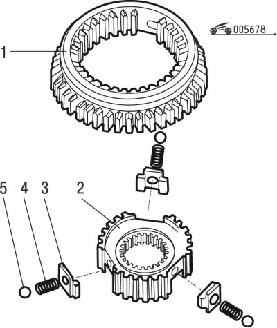
Pic. 6.78. Synchronizer 1st and 2nd gears (first option): 1 - clutch with gear; 2 - synchronizer hub; 3 - cracker; 4 - spring; 5 - ball
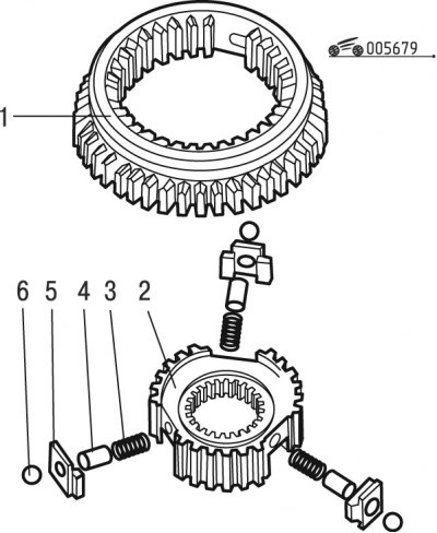
Pic. 6.79. Synchronizer 1st and 2nd gears (second option): 1 - clutch with gear; 2 - synchronizer hub; 3 - spring; 4 - pin; 5 - cracker; 6 - ball
Synchronizers of the 1st and 2nd gears of two options are installed in the gearbox of the Peugeot 206 car (pic. 6.78 and 6.79). The design of the synchronizer of the 3rd and 4th gears is similar to the design of the second option.
Disassemble the synchronizer in the following order:
- mark relative position of coupling 1 (see fig. 6.78) and hubs 2 in order to install them in the same position during assembly;
- remove the synchronizer sleeve from the hub and all its parts.
Assemble the synchronizer in the version according to the first option in the following order:
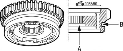
Pic. 6.80. Orientation of the synchronizer sleeve relative to the hub: A - groove; B - groove
- orient the clutch and synchronizer hub as shown in fig. 6.80: groove A on the hub should be oriented in the same direction as groove B on the coupling, while also orienting it according to the marks made during disassembly;
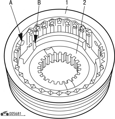
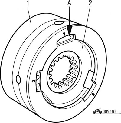
Pic. 6.81. Installing the Clutch and Synchronizer Hub: 1 - clutch; 2 - hub; A, B - grooves
- when assembling, it is necessary that the groove A of the coupling 1 (pic. 6.81) coincided with the groove B on the hub 2;
- slide the coupling relative to the hub;
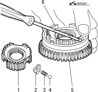
Pic. 6.82. Synchronizer assembly: 1 - hub; 2 - cracker; 3 - spring; 4 - ball; 5 - clutch; 6 - hub
- put crackers 2 in succession in their places (pic. 6.82), springs 3 and balls 4, then move the clutch to the neutral position.
Assemble the synchronizer in the version according to the second option using the tool in the following order:
- when assembling, orient the clutch and synchronizer hub as shown in fig. 6.80: groove A on the hub should be oriented in the same direction as groove B on the coupling, while also orienting it according to the marks made during disassembly;
- when assembling, it is necessary that the groove A of the coupling 1 (see fig. 6.81) coincided with the groove B on the hub 2;
Pic. 6.83. Installing the hub in the fixture: 1 - fixture; 2 - hub; A - groove
- install hub 2 (pic. 6.83) into the fixture so that the groove of the hub coincides with the hole in the fixture;
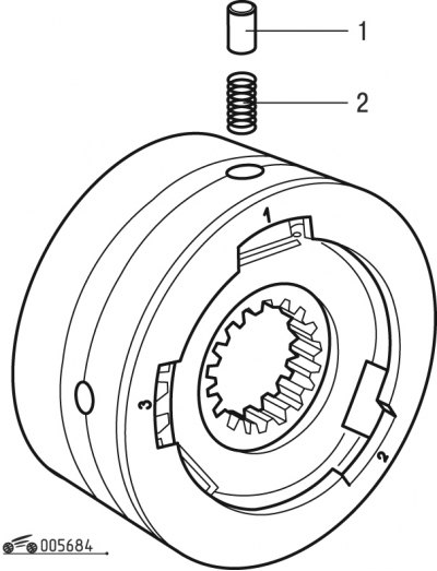
Pic. 6.84. Installing the spring and pin: 1 - pin; 2 - spring
- reinstall springs 2 (pic. 6.84) and pins 1;
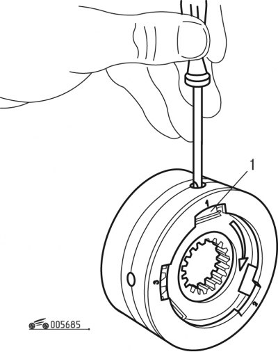
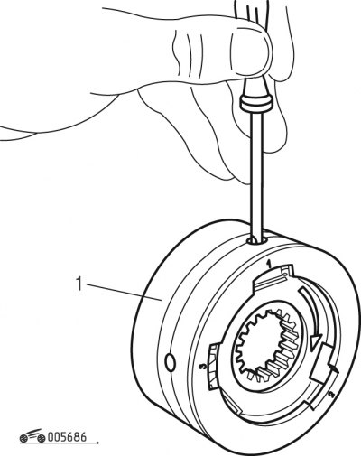
Pic. 6.85. Dryer installation: 1 - cracker
- using a screwdriver, press on the pins and insert crackers 1 into the grooves of the hub (pic. 6.85);
Pic. 6.86. Fixture Rotation: 1 - fixture
- insert the balls into the holes of tool 1 (pic. 6.86), after that, pressing on the balls with a screwdriver, turn the fixture so that the balls do not pop out;
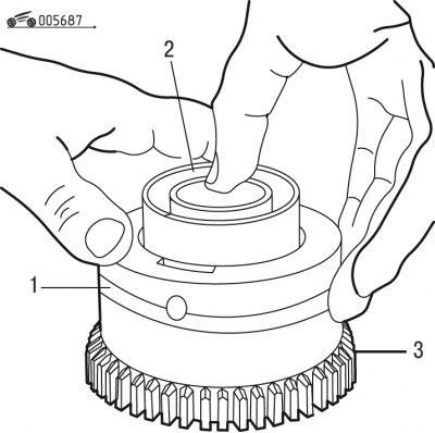
Pic. 6.87. Synchronizer Assembly (Option 2): 1, 2 - fixtures; 3 - clutch
- install clutch 3 (pic. 6.87) serrated surface on the workbench;
- install the assembled device 1 on the coupling, observing the marks made during disassembly;
- insert the synchronizer hub into the clutch 3 by pressing the fixture 2 with your hand.