
- three-jaw puller - Facom U20;
- bushing for tightening the output shaft nut.
Removing the intermediate gearbox housing is carried out in the following order:
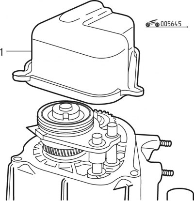
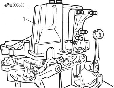
Pic. 6.45. Stamped gearbox cover: 1 - cover
- remove stamped cover 1 (pic. 6.45);
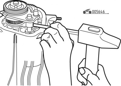
Pic. 6.46. Knocking out the pin of the 5th gear fork
- knock out the pin of the 5th gear fork with the stem (pic. 6.46);
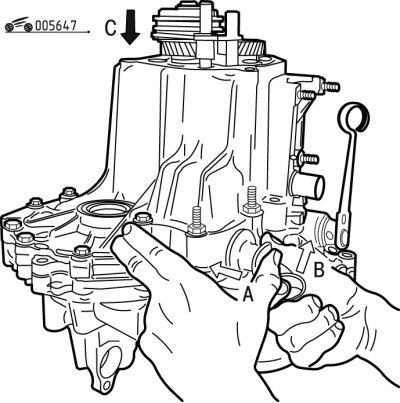
Pic. 6.47. Fixation of the secondary shaft from grumbling
- fix the output shaft from turning, to do this, select the lever and engage reverse, and then 5th gear by pressing the 5th gear fork (pic. 6.47);
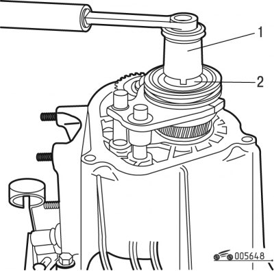
Pic. 6.48. Unscrewing the nut of the output shaft: 1 - fixture; 2 - nut
- unscrew special nut 2 (pic. 6.48) output shaft using tool 1;
Note. The gearbox can be designed with a conventional hex nut without a lock washer.
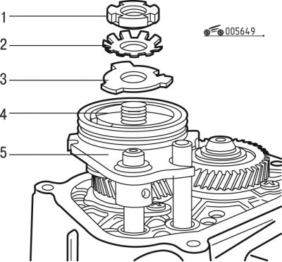
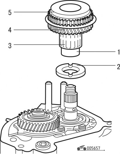
Pic. 6.49. Fastening of the synchronizer of 5th transfer: 1 - nut; 2 - spring washer; 3 - support washer; 4 - 5th gear synchronizer clutch; 5 - 5th gear engagement fork
- remove spring washer 2 (pic. 6.49) and support washer 3;
- remove the clutch 4 of the synchronizer of the 5th gear together with the fork 5 of the 5th gear;
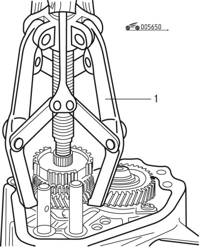
Pic. 6.50. Removing the 5th gear synchronizer hub with gear: 1 - puller
- with puller 1 (pic. 6.50) press the synchronizer hub together with the 5th gear;
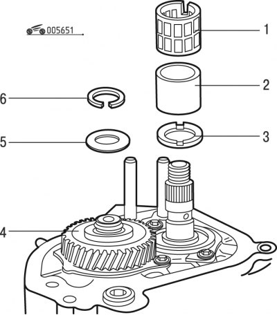
Pic. 6.51. Details of primary and secondary shafts: 1 - needle bearing; 2 - bushing; 3 - washer; 4 - gear wheel of the 5th gear; 5 - spring washer; 6 - retaining ring
- remove the circlip 6 from the input shaft (pic. 6.51) with spring washer 5;
- remove the needle bearing 1, bushing 2 and washer 3 from the secondary shaft;
- press the 4th fifth gear from the input shaft with a puller;
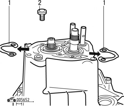
Pic. 6.52. Stop plates: 1 - locking plates; 2 - bolt
- unscrew bolts 2 (pic. 6.52) fastening of locking plates 1 bearings and remove them;
Pic. 6.53. Removing the intermediate gearbox housing: 1 - intermediate crankcase
- unscrew the bolts securing the intermediate crankcase 1 (pic. 6.53) to the clutch housing with differential;
- remove the intermediate housing.
Install the intermediate gearbox housing in the following order:
- lubricate the mating surface of the gearbox housing with a thin layer of E15;
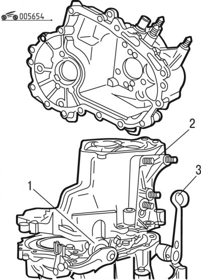
Pic. 6.54. Intermediate crankcase installation: 1 - sealing ring; 2 - crankcase; 3 - clutch release lever
- reinstall sealing ring 1 (pic. 6.54) the gearshift shaft and put the clutch release lever 3 in the correct position;
- install intermediate crankcase 2;
Note. Bolts of fastening of a case with a directing belt establish according to marking.
- install the crankcase mounting bolts and tighten them to a torque of 17.5 Nm;
- clean the threaded holes in the crankcase with a tap;
- install locking plates 1 (see fig. 6.52) bearings chamfer up;
- install new bolts 2 in place, having previously applied grease to them;
- tighten the bolts to 17.5 Nm;
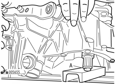
Pic. 6.55. Installing the gearbox on the press table: A - the end of the input shaft
- install end A (pic. 6.55) the input shaft on the stop on the press table;
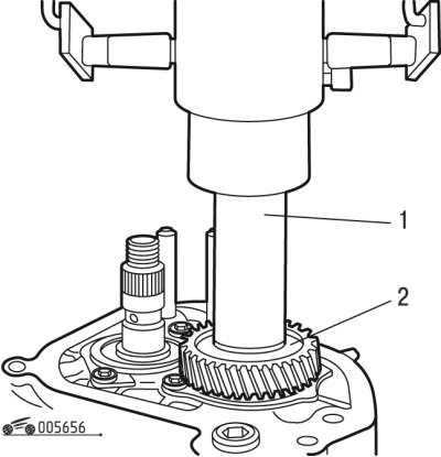
Pic. 6.56. Installing the 5th gear on the input shaft: 1 - press; 2 - 5th gear
- press on pinion 2 (pic. 6.56) fifth gear on the input shaft;
- install a new spring washer 5 (see fig. 6.51) on the input shaft;
- install a new retaining ring 6 using the tool;
Pic. 6.57. Installing the driven gear of the 5th gear on the secondary shaft: 1 - bushing; 2 - washer; 3 - needle bearing; 4 - gear wheel of the 5th gear; 5 - synchronizer ring
- install washer 2 on the secondary shaft (pic. 6.57), sleeve 1, needle bearing 3;
- install the gear wheel 4 of the fifth gear with the ring 5 of the synchronizer on the needle bearing;
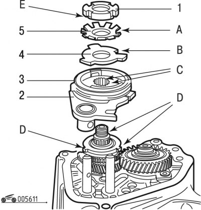
Pic. 6.58. Fastening parts of the secondary shaft with a nut: 1 - nut; 2 - 5th gear engagement fork; 3 - 5th gear synchronizer; 4 - support washer; 5 - spring washer; A - ledge; B - slot; C - grooves; D - protrusions; E - chamfer
- install plug 2 (pic. 6.58) together with synchronizer 3 of the fifth gear in its place;
Attention! Insert the protrusions D of the sleeve into the grooves C of the synchronizer.
- replace nut 1 with the friction washer and slotted nut supplied as spare parts;
- replace support washer 4 if it does not have slot B;
Attention! Align lug A of the washer against slot B of the support washer. Install the nut 1 so that the chamfer E is directed towards the spring washer 5.
- fix the output shaft from turning, to do this, select the lever and engage reverse, and then 5th gear by pressing the 5th gear fork (see fig. 6.47);
- tighten the output shaft nut to 137.5 Nm, loosen slightly if necessary to align the lip of the washer with the cutout of the nut;
- set the gear lever to neutral position;
- lock nut 1 (see fig. 6.58) protrusion A of washer 5 so that it enters the cutout of the nut;
- secure the 5th shift fork by installing a new pin (see fig. 6.46);
- install stamped cover 1 (see fig. 6.45) with new gasket;
Attention! Do not lubricate the gasket.
- tighten bolts of fastening of a cover the moment of 23 Нм.