



Table of contents: Cars with EW10J4/EW12J4 engines 🠇 Cars with the ES9J4S engine 🠇
Cars with EW10J4/EW12J4 engines
Removal
1. Remove the windshield wiper, timing belt and engine protective cover, see the relevant chapter.
2. Disconnect the crankcase ventilation hose 1 (see illustration).
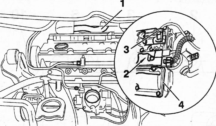
5.2. Disconnect the crankcase ventilation hose 1
3. Disconnect the plugs and remove the ignition coils 2, the camshaft position sensor 3, and both parts 4 of the cylinder head cover from the cylinder head by unscrewing the mounting bolts (see illustration 5.2).
4. Remove the thrust rollers that were used to lock the camshafts when removing the timing belt.
5. Place key A on the hexagon of the camshaft to prevent the shaft from turning, and use the appropriate key to unscrew the central bolt 6, which secures the gear hub to the camshaft (see illustration).
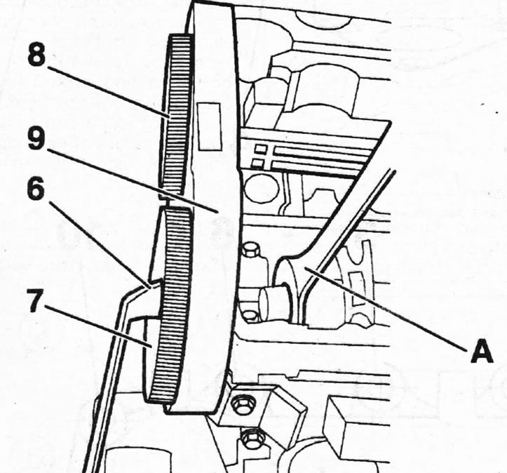
5.5. Unscrew the central bolt 6 securing the gear hub to the camshaft, holding the shaft from turning with key A
Caution! If the engine is equipped with an intake camshaft position adjuster, remove the central bolt securing the adjuster and gear to the camshaft. Subsequently, the regulator can be removed from the gear by unscrewing the mounting bolts 1 (see illustrations 5.5a and 5.5b).
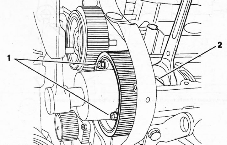
5.5a Gear with intake camshaft position adjuster
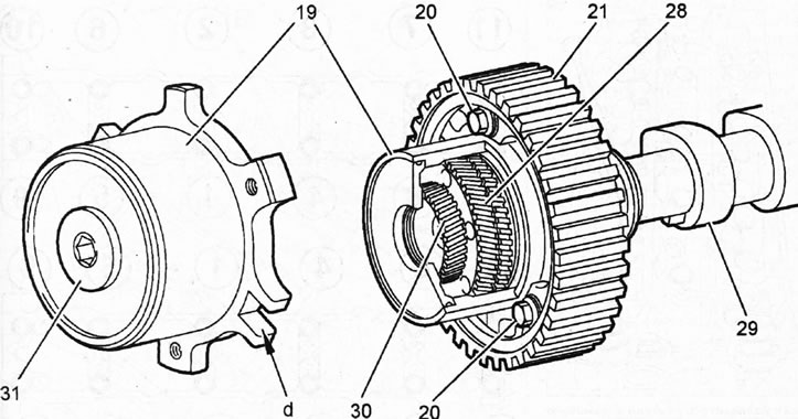
5.5b Camshaft position regulator 19 20 - bolts securing the regulator to the camshaft gear; 21 - camshaft gear 28 - piston; 29 - intake camshaft; 30 - regulator hub; 31 - regulator mounting bolt plug d - support recess
6. Remove both gears from the camshafts by unscrewing the central gear mounting bolt 8 (see illustration 5.5).
7. Remove the rear cover 9 of the timing drive (see illustration 5.5).
8. Working in a spiral motion, starting with the outer bolt, loosen the camshaft bearing housing bolts until the bolt heads are a few millimetres clear of the housing, then remove the bolts completely and remove the camshaft bearing housings.
9. Remove both camshafts by tapping them from the clutch side and remove their seals (see illustration).
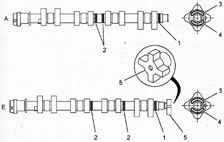
5.9. Camshafts. Cars with EW10J4 engine
10. Mark the tappets and their mounting locations if they will be removed, so that you can then install each one in its place.
11. Remove the pushers using a suction cup (see illustration).
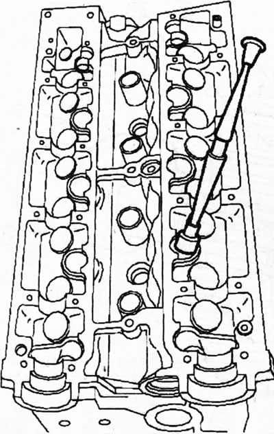
5.11. Remove the pushers using a suction cup
Installation
12. Install the tappets, if removed, each one in its seat, having previously lubricated them. Check the ease of movement of the tappets in the cylinder head.
View the original on the website (peugeotbook.ru)
13. Lubricate the surfaces of the bearing housings that mate with the camshaft journals with a small amount of engine oil.
14. Make sure that the centering pins 10 are in their mounting locations on the cylinder head (see illustration).
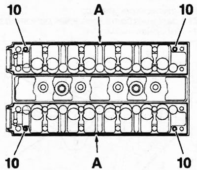
5.14. Make sure that the centering pins 10 are in their mounting locations on the cylinder head
15. Place the camshafts in their seats.
Caution! The camshaft position sensor gear must be installed on the exhaust camshaft if this gear was removed (see illustration 5.9).
16. Apply sealant around the perimeter A of the bearing housing (see illustration 5.14) and install the housings.
Attention! The exhaust camshaft bearing housing has a hole for the camshaft position sensor.
17. Screw in and tighten the mounting bolts in several passes in ascending order of their numbering (see illustration):
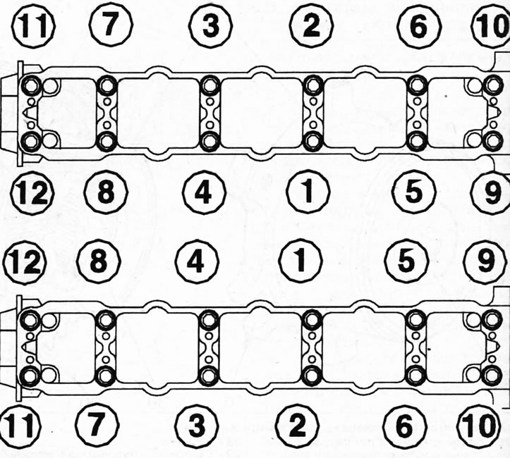
5.17. The order of tightening the bolts for fastening the camshaft bearing housings
- 1st pass - tighten the bolts by hand;
- 2nd pass - tighten the bolts to 5 Nm;
- 3rd pass - tighten the bolts to 10 Nm.
18. Install the timing drive protective cover.
19. Make sure that the camshaft oil seal seats are clean and dry, without any traces of sealant. Pack new seals with suitable mandrels.
The installation of the remaining dismantled components is carried out in the reverse order of removal.
Cars with the ES9J4S engine
Removal
20. Remove the right support of the power unit.
21. Remove the timing belt, see the relevant chapter.
22. Move aside the wiring harness and the hoses that block access to the cylinder head covers, disconnect the lugs 2, unscrew the mounting bolts and remove the covers 3a and 3b from both cylinder heads (see illustration).
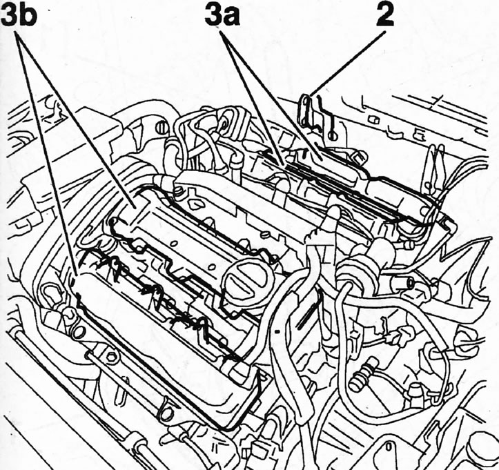
5.22 Disconnect lugs 2, unscrew the mounting bolts and remove covers 3a and 3b from both cylinder heads
23. Remove the intake manifold from the right (rear) cylinder head to allow removal of the head cover.
24. Remove the plug that closes the intake camshaft position adjuster on each cylinder head, unscrew the central bolt securing the adjuster 3 and the gear hub to the camshaft with a 2 x 14 mm socket wrench, holding the camshaft from turning with a 1 Allen key 1, and remove the adjuster together with the gear (see illustration).
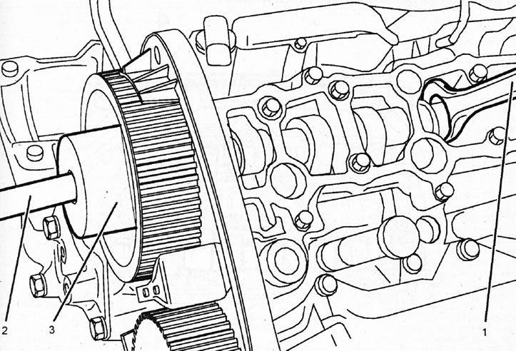
5.24. Unscrew the central bolt securing the regulator 3 and the gear hub to the intake camshaft with a 2 x 14 mm socket wrench, holding the camshaft from turning with a 1 Allen key
25. Remove gears 1 and their hubs from the exhaust camshafts by unscrewing the central mounting bolts, while holding the gear from turning with the tool [1] (see illustration).
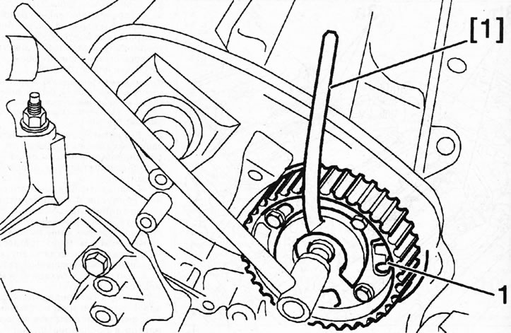
5.25. Remove gears 1 and their hubs from the exhaust camshafts by unscrewing the central mounting bolts, while holding the gear from turning with the tool [1]
Caution! The central bolts securing the gears to the camshafts have left-hand threads, so unscrew them clockwise.
26. Unscrew the bolts securing the timing gear protective covers to the camshafts and remove them.
27. Unscrew the mounting bolts of the 4 camshaft bearing housings 5, remove the housings and take out the camshafts together with the oil seals (see illustration). The intake camshafts are marked with the letter A, and the exhaust camshafts with the letter E (see illustration 5.27a).
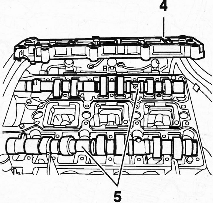
5.27. Unscrew the mounting bolts of the 4 camshaft bearing housings 5, remove the housings and take out the camshafts together with the oil seals
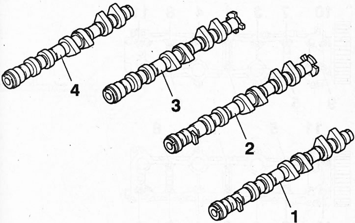
5.27a. Camshafts of the ES9J4S engine 1 - exhaust camshaft of the left cylinder head (E389); 2- camshaft of the intake valves of the left cylinder head (A423); 3 - camshaft of the intake valves of the right cylinder head (A423); 4 - exhaust camshaft of the right cylinder head (E389)
Installation of camshafts and intake valve position adjusters is performed in the reverse order of their removal.
28. Install the hydraulic tappets in their places, if they were removed, lubricating them with MOLYDAL GB SP 370G.
29. Install the camshafts, lubricating their bearing journals with MOLYDAL GBSP370G.
30. Make sure that the centering pins 6 are in their mounting locations on the cylinder head (see illustration).
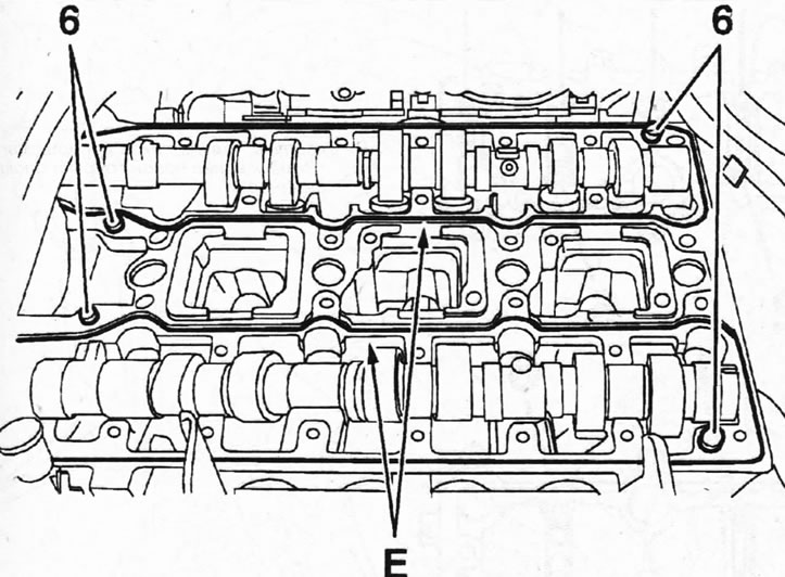
5.30. Make sure that the centering pins 6 are in their mounting locations on the cylinder head
31. Apply AUTOJOINT OR sealant to the surfaces of the cylinder head E that mate with the bearing housings (see illustration 5.30).
32. Install the bearing housings, screw in and tighten the bolts, acting in the ascending order of the bolt numbers (see illustration). Tightening of bolts is performed in two passes:
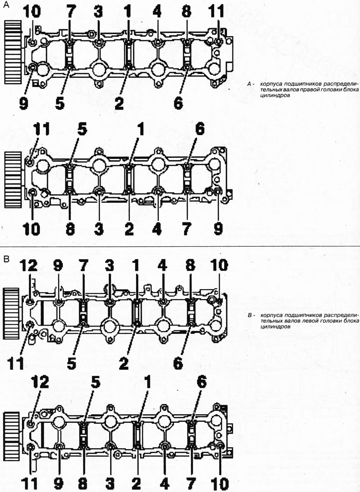
5.32. Install the bearing housings, screw in and tighten the bolts for fastening them, acting in ascending order of numbering
- Pass 1: Tighten the bolts to 2 Nm;
- Pass 2: Tighten the bolts to a final torque of 8 Nm.
33. Install the rear timing cover and drive in new camshaft seals using a suitable mandrel 2 (see illustration).
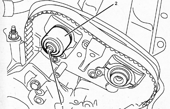
5.33. Install new camshaft seals using a suitable mandrel 2 1 - central gear mounting bolt. It must be replaced with a new one
34. Install gears 1 on the camshafts and secure them with new bolts, lubricating their threads and the lower part of the heads with MOLYKOTEG RAPID PLUS grease. The gears are installed on the intake camshafts together with the camshaft position adjusters. Tightening torque of the bolts is 20 Nm + additional rotation of 57°. When tightening the bolts, hold the gears from turning with stop 2 (see illustration).
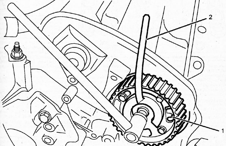
5.34. Install gears 1 on the camshafts and secure them with new bolts, holding them from turning with stop 2
Caution! The gears on the hubs must be installed so that the protrusion C on the intake camshaft gear faces away from the cylinder head, and on the exhaust camshaft gear - towards the cylinder head (see illustration 5.34a).
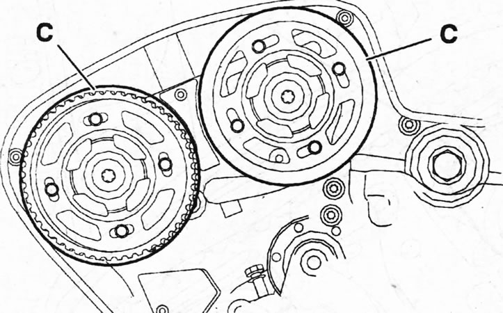
5.34a. The projection C on the intake camshaft gear should be facing away from the cylinder head, and on the exhaust camshaft gear - towards the cylinder head
35. Install the cylinder head covers.
The installation of the remaining removed components is carried out in reverse order.
Disassembling the cylinder head
Attention! Cylinder head disassembly is shown using the EW12J4 engine as an example.
36. Disconnect the plug and remove the ignition coil block.
37. Unscrew spark plugs 5, bolts securing covers 2 and 7 of the cylinder head and remove the covers (see illustration).
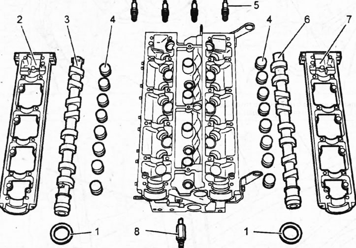
5.37. Unscrew spark plugs 5, bolts securing covers 2 and 7 of the cylinder head and remove the covers
38. Unscrew the camshaft bearing housing mounting bolts, remove the housing, take out camshafts 3 and 6 and remove their oil seals 1 (see illustration 5.37).
39. Remove the rocker arm shaft, take out the hydraulic tappets 4 and disconnect the electromagnetic valve 8 of the intake camshaft position adjuster (see illustration 5.37). Before removing, mark the pushers so that they can be installed in their original locations during assembly.
Caution! Mark the valves and their mounting locations before removing the valves.
40. Release the valves from the crackers by compressing the valve springs with special tool 1, then remove the springs with the plates and take out the valves (see illustrations 5.40 and 5.40a).
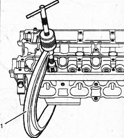
5.40. Release the valves from the crackers by compressing the valve springs with special tool 1, then remove the springs with the plates and take out the valves
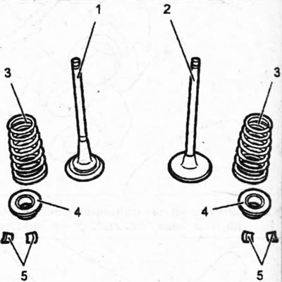
5.40a. Valve components 1 - exhaust valve; 2 - inlet valve; 3 - valve spring; 4 - valve spring plate; 5 - valve crackers
Please note: Inlet and outlet valve springs are interchangeable.
41. Remove the oil deflector caps 1 from the valve guide bushings using special pliers 2 (see illustration). When installing new oil deflector caps, they are pressed in using a suitable mandrel.
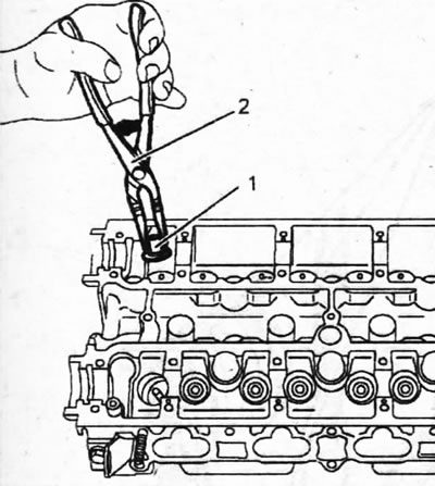
5.41. Remove the oil deflector caps 1 from the valve guide bushings using special pliers 2
42. Clean the one-pass (non-refundable) valve "a" and the surface around it, and then blow out valve "b" with compressed air through a 6.5 mm diameter nozzle (see illustration).
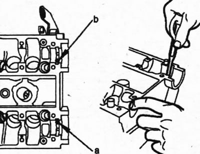
5.42. Clean the one-way (non-refundable) valve "a" and the surface around it, and then blow out valve "b" with compressed air
43. Remove, if necessary, the non-return valve 1 from the mounting hole on the cylinder head (see illustration).
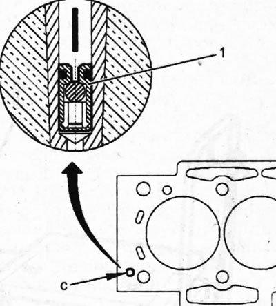
5.43. Remove the non-return valve 1 from the mounting hole on the cylinder head
44. Clean the cylinder head and check it for warpage. It is recommended to clean the sealing surfaces of the cylinder head with a special agent, for example, DECAPLOC 88.
45. Check the condition of the valve seats and their guides, valve springs, camshafts, camshaft bearing housing, and hydraulic tappets (see illustration). If necessary, re-thread the cylinder head bolt holes and replace any worn or damaged parts.
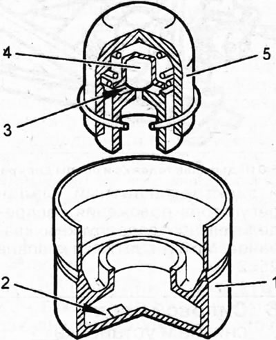
5.45. Check the condition of the hydraulic tappets 1 - pusher body; 2 - low pressure chamber; 3 - high pressure chamber; 4 - valve ball; 5 - piston
The cylinder head is assembled in the reverse order of disassembly.
46. Compress the valve spring with a special tool. Insert crackers into the grooves on the protruding upper end of the valve stem and carefully release the special device. Make sure the crackers are firmly in place. The intake and exhaust valve crackers are the same.
To check the seating of the crackers, tap the top of the valve stems with a plastic hammer. Incorrectly installed crackers pop out upon impact. To prevent parts from flying out, place a rag on the valve spring.
47. Tap new valve stem seals onto the valve guides using mandrel 1.
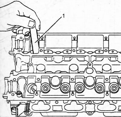
5.47. Tap new valve stem seals onto the valve guides using mandrel 1
48. Press in the camshaft seals 1 using the appropriate mandrel 3, which is pressed by the central bolt 4 securing the gear to the camshaft (see illustration). In workshops, two mandrels are used for this purpose, one of which is auxiliary and is intended for installation on the pressing mandrel (see illustration 5.48a).
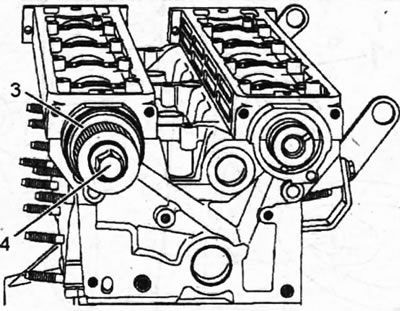
5.48. Press in the seals 1 of the camshafts using the appropriate mandrel 3, which is pressed by the central bolt 4 securing the gear to the camshaft
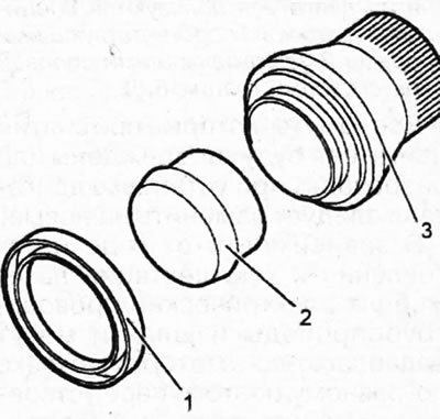
5.48a. Mandrels for installing camshaft seals 1 - oil seal; 2 - auxiliary mandrel; 3 - pressing mandrel
49. Screw in the spark plugs and the intake camshaft position adjuster solenoid valve. Valve tightening torque 25+2 Nm.