



Table of contents: Cars with EW10J4 engine 🠇 Cars with the ES9J4S engine 🠇
Necessary tools and equipment (see illustration 4.0):
- 1 - hose with adapter for relieving pressure in the fuel rail (0141-T1);
- 2 - socket head for unscrewing the cylinder head mounting bolts (0185)
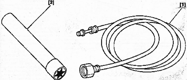
4.0. Tools and fixtures for removing the cylinder head
Cars with EW10J4 engine
Removal
1. Remove the windshield wiper mechanism, see the relevant chapter.
2. Drain the coolant, see the relevant chapter.
3. Disconnect the exhaust pipe from the exhaust manifold, see the relevant chapter.
4. Disconnect hose 1 from the back of the thermostat housing (see illustration).
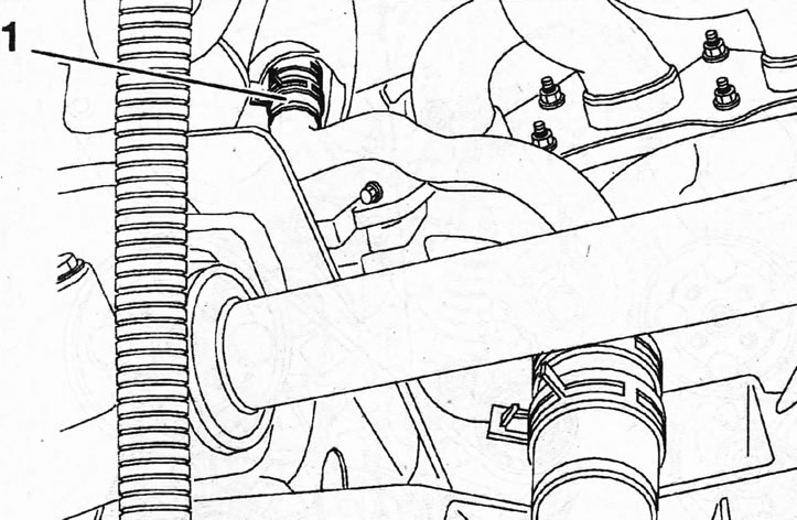
4.4. Disconnect hose 1 on the back of the thermostat housing
5. Disconnect the connector "a" of the engine oil pressure sensor and the connector "b" of the air conditioning compressor (see arrows in the illustration).
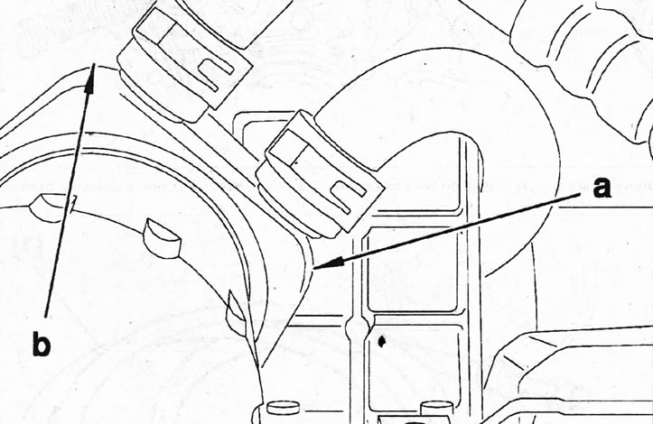
4.5. Disconnect the connector "a" of the engine oil pressure sensor and the connector "b" of the air conditioning compressor (see arrows)
6. Remove the engine protective cover.
7. Disconnect the negative (-) battery terminal from the battery.
8. Disconnect the supply air duct from the throttle valve and air filter.
9. Unscrew the mounting bolts and remove the coolant expansion tank.
10. Disconnect the outlet hose from the thermostat housing.
11. Disconnect the heater supply hose from the thermostat housing.
12. Remove the timing belt, see the relevant chapter.
13. Remove the timing belt tension roller 2 and unscrew the bolt 3 (see illustration).
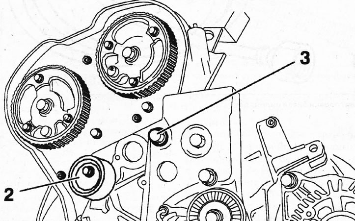
4.13. Remove the timing belt tension roller 2 and unscrew the bolt 3
14. Connect a hose with adapter 0141-T to the valve on the fuel supply line and release the pressure, and collect the leaked fuel.
15. Disconnect the fuel lines and the accelerator cable from the throttle lever.
16. Disconnect the throttle body heater plug, intake manifold air pressure sensor plug, intake air temperature sensor plug, throttle opening potentiometer plug, and idle speed control valve motor plug.
18. Unscrew the mounting bolt and remove the wiring harness holder from the cylinder head.
19. Disconnect the low pressure hose of the brake booster from the intake manifold.
20. Disconnect the engine wiring harness plug 4 from the fuse and relay box in the engine compartment. The plug is located near the right headlight (see illustration).
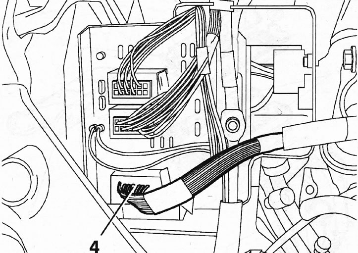
4.20. Disconnect plug 4 of the engine wiring harness near the right headlight from the fuse and relay box
Source of the article is posted at: peugeotbook.ru
21. Disconnect the EGR solenoid valve plug, the camshaft position sensor plug, the ignition coil assembly plug, and the coolant temperature sensor plug located on the cylinder head.
22. Disconnect the wiring harness holder from the thermostat housing and move the harness away from the work area.
23. Disconnect the exhaust gas return line 5 for afterburning from the intake manifold and the crankcase ventilation hose 6 from the cylinder head (see illustration).
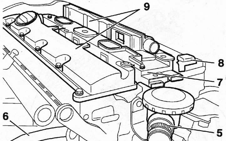
4.23. Disconnect the exhaust gas return line 5 for afterburning from the intake manifold and the crankcase ventilation hose 6 from the cylinder head
24. Remove the ignition coil block 7, the camshaft position sensor 8 and both parts 9 of the cylinder head covers (see illustration 4.23).
25. Disconnect the intake manifold 1 from the cylinder head and remove its gasket 5 (see illustration).
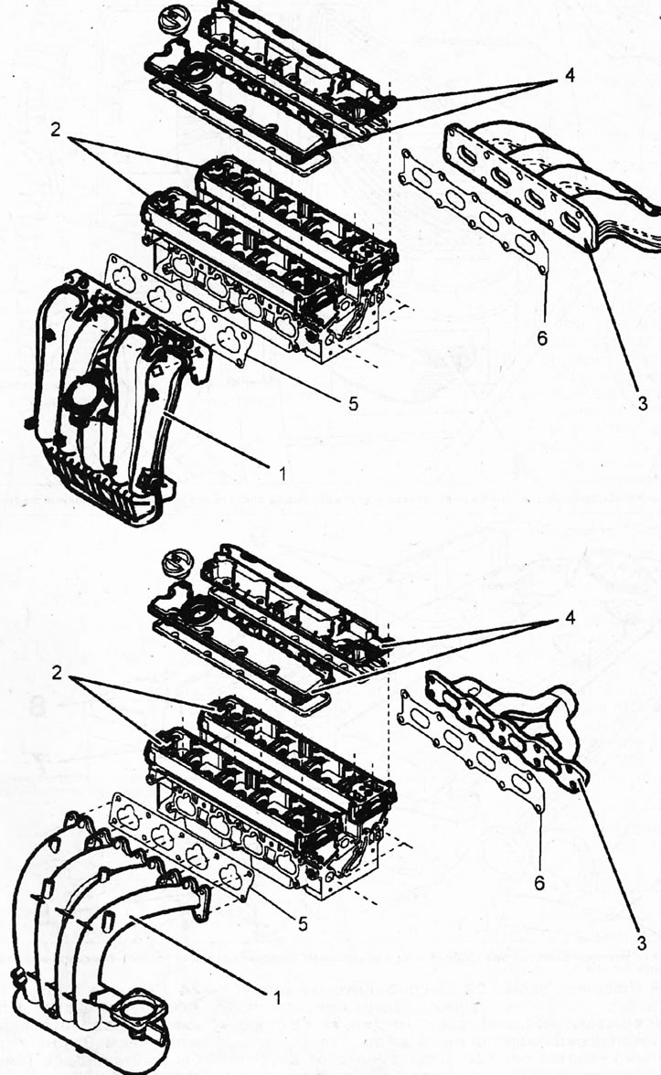
4.25. Disconnect the intake manifold 1 from the cylinder head A - EW10J4 engine; B - EW12J4 engine; 2 - camshaft bearing housings; 3 - exhaust manifold; 4 - cylinder head covers with sealing gaskets; 5 - intake manifold sealing gasket; 6 - exhaust manifold sealing gasket
26. Loosen the cylinder head mounting bolts in ascending order of numbering, then unscrew them and remove the cylinder head and sealing gasket (see illustrations 4.26 and 4.26b). On the cylinder head there are corresponding marks and designations a, b and c, which determine the manufacturer of the head, the composition of its material (casting), etc. (see illustration 4.26a and 4.26b).
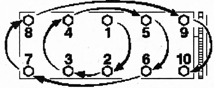
4.26 Sequence of unscrewing the cylinder head mounting bolts. Cars with EW10J4/EW12J4 engines
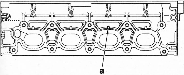
4.26a Marks on the cylinder head a - (manufacturer) on the upper surface of the head. The material (casting) designation is located on the side of the head to which the exhaust manifold is attached

4.26b Cylinder head. Cars with EW10J4 engine 1 - cylinder head cover; 2- camshaft bearing housing; 3 - cylinder head
Installation
27. Clean the mating surfaces of the cylinder head and block.
Caution: Use a plastic or wooden scraper to clean the aluminum alloy. We recommend using DECAPJOINT cleaning agent. Do not use sharp-edged tools to clean the cylinder head. Prevent dirt from entering the cylinder bores. Plug their holes with a clean rag. Clean the channels if necessary.
28. Check the cylinder head for deformation and warpage using a standard steel ruler (see illustration) Permissible cylinder head deformation should not exceed 0.05 mm. The cylinder head can be reworked. The residual height of the cylinder head after grinding should not be less than 136.7+0.05 mm. The nominal height A of the head is 137+0.05 mm (see illustration 4.28a). The d mark, indicating the possibility of resurfacing the cylinder head, is applied to the side of the head that is located near the timing belt (see illustration 4.286). Since the maximum thickness of metal that can be removed during processing is 0.3 mm, this figure is stamped on the head. If it is possible to drill holes in the camshaft bearing housing for the mounting bolts, then the d mark on the head consists of the number 0.3 and the letter A (0.3A).
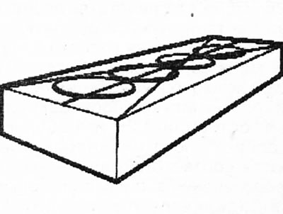
4.28. Check the cylinder head for deformation and warping using a standard steel ruler.
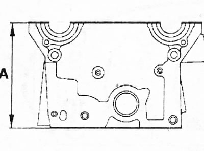
4.28a. Height A of the cylinder head
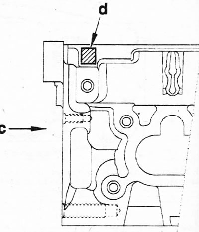
4.28b Location of the d mark on the cylinder head indicating the possibility of head modification c - side of the head near the timing belt
29. Clean the threads in the holes for the cylinder head mounting bolts. These holes should be free of oil or other contaminants. If necessary, blow out the holes with compressed air or clean them with a screwdriver wrapped in a rag that will absorb the liquid. Oil can be collected from the holes using a grease gun. Failure to do so will create excess pressure in the holes when tightening the bolts, which could lead to a rupture of the cylinder block or improper tightening of the bolts.
30. Measure the length of the cylinder head mounting bolts. The length of their rods X, measured from the bottom surface of the bolt head, should not exceed 129.0 mm (see illustration). Otherwise, the bolts should be replaced with new ones. The length of the new bolt shaft is 127.5 mm, and the length of the new washer is 4.0±0.2 mm
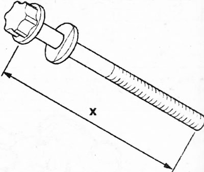
4.30. Measure the length X of the cylinder head bolts
31. Make sure that the centering pins 10 are in their places on the cylinder block (see illustration).
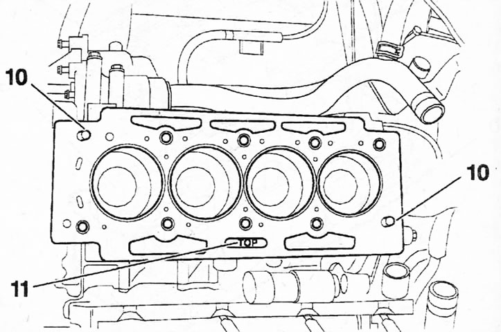
4.31 Make sure that the centering pins 10 are in their places on the cylinder block Vehicles with engine EW10J4/EW12J4
Caution! The cylinder head gasket must be replaced with a new one. Metallized gasket. The thickness of the cylinder head gasket is indicated by the corresponding number of holes. When replacing an old gasket with a new one, it should have the same number of holes as the old one, unless the pistons or other components that affect the thickness of the gasket have been replaced (see illustration 4.0a).
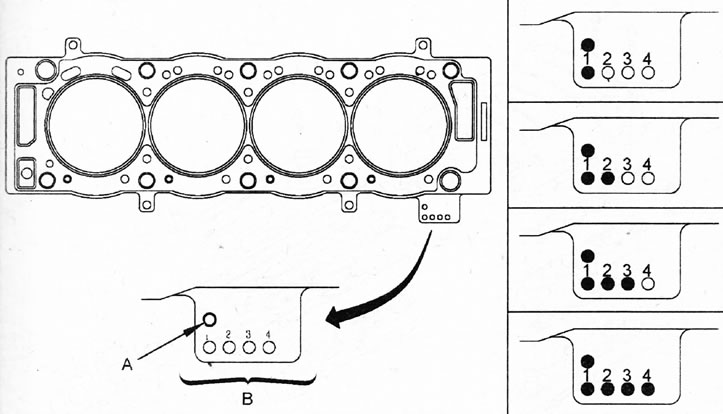
4.0a. Marking of the cylinder head gasket for EW10J4/EW12J4 engines
32. Place the new cylinder head gasket 11 on the cylinder block so that the "TOP" inscription on it faces up (see illustration 4.31). A cylinder head gasket may have up to five notches or holes.
33. Install the head on the cylinder block and screw in the head mounting bolts, having previously lubricated the threads and the lower part of the bolt heads with MOLYKOTEG RAPID PLUS (see illustration).
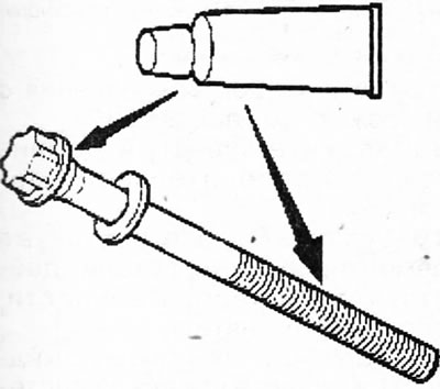
4.33. Lubricate the threads and the underside of the bolt heads with MOLYKOTE G RAPID PLUS
34. Tighten the cylinder head bolts in several passes, acting in ascending order of their numbers (see illustration):
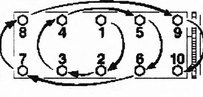
4.34. Sequence of tightening the cylinder head bolts. Cars with EW10J4/EW12J4 engines
- 1st pass - 15 Nm;
- 2nd pass - 50 Nm;
- 3rd pass - loosen the bolts one full turn;
- 4th pass - 20 Nm;
- 5th pass - tighten the bolts by 285°.
Attention! The rotation angle of the cylinder head bolts for EW12J4 engines is 270°.
35. Screw in bolt 10, which secures the ignition coil block bracket to the cylinder head, and tighten it to 45 Nm (see illustration 4.36).
36. Place the cylinder head covers on the cylinder head together with the new sealing gaskets and secure the covers with bolts, tightening them in ascending numbering sequence in two passes (see illustration):
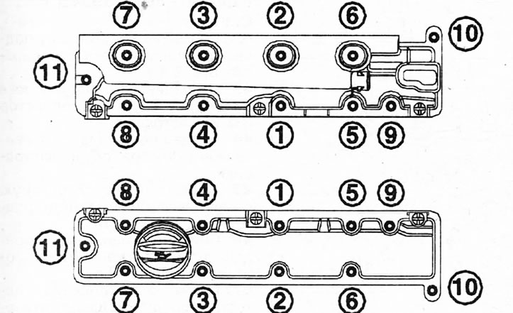
4.36. Sequence of tightening the cylinder head cover bolts. Cars with EW10J4/EW12J4 engines
- Pass 1: Tighten the bolts to 5 Nm;
- Pass 2: Tighten the bolts to 11 Nm.
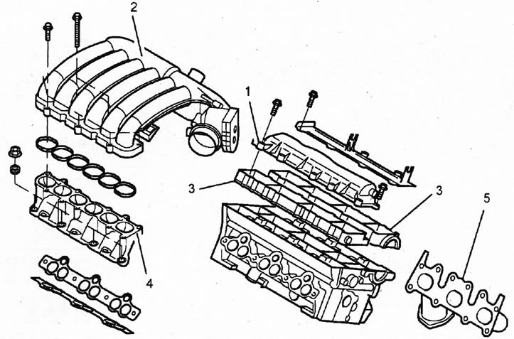
4.36. Sequence of tightening the cylinder head cover bolts. Cars with EW10 J4/EW12J4 engine 1 - cylinder head cover; 2 - intake manifold; 3 - camshaft bearing housing; 4 - intake manifold sealing gasket; 5 - exhaust manifold
37. Install the camshaft position sensor and ignition coil assembly.
38 Install the intake manifold.
39. Install the timing belt.
40. Install all other removed parts in the reverse order of their removal.
41. Fill with coolant and bleed air from the cooling system.
Cars with the ES9J4S engine
Removal
42. Remove the right power unit suspension support (see illustration 2.31).
43. Disconnect the intake manifold from the cylinder head (see illustration).
44. Disconnect the crankcase ventilation hoses 1 (see illustration).
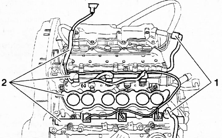
4.44. Disconnect the crankcase ventilation hoses 1
45. Disconnect the fuel rail and plug the holes with suitable plugs.
46. Remove the timing belt, see the relevant chapter.
47. Drain the coolant, disconnect the hoses from the thermostat housing and remove the thermostat housing 3 (see illustration).
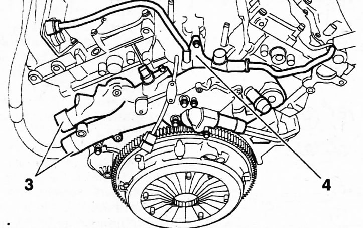
4.47. Remove the thermostat housing 3 4 - crankcase ventilation pipes
48. Remove the engine oil level indicator rod (dipstick), disconnect its guide tube 5, and also remove the holders 6 of the power steering pipes (see illustration). Tightening torque of holder bolts: 25 Nm.
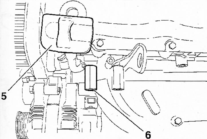
4.48. Remove the engine oil level indicator (dipstick), disconnect its guide tube 5, and also remove the holders 6 of the power steering pipes
49. Unscrew the mounting bolts and remove gears 7 from the camshafts (see illustration).
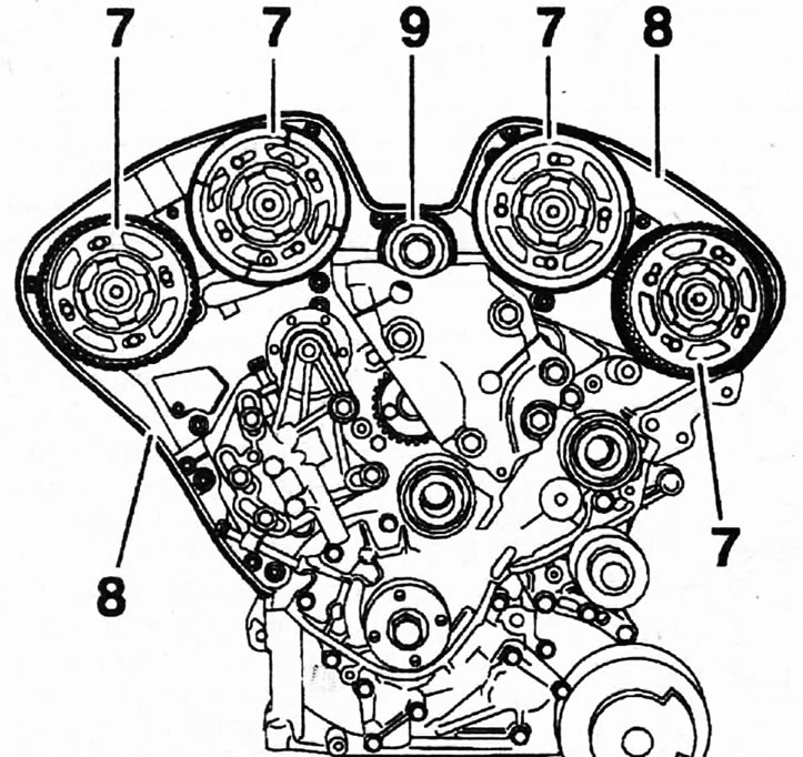
4.49. Unscrew the mounting bolts and remove gears 7 from the camshafts
50. Remove the rear covers 8 of the timing drive and the tension roller 9 of the toothed belt (see illustration 4.49).
51. Unscrew the mounting bolts and remove the cylinder head cover.
52. Unscrew the cylinder head mounting bolts, acting in a spiral, and remove, depending on necessity, cylinder head 10 or 11 or both (see illustration).
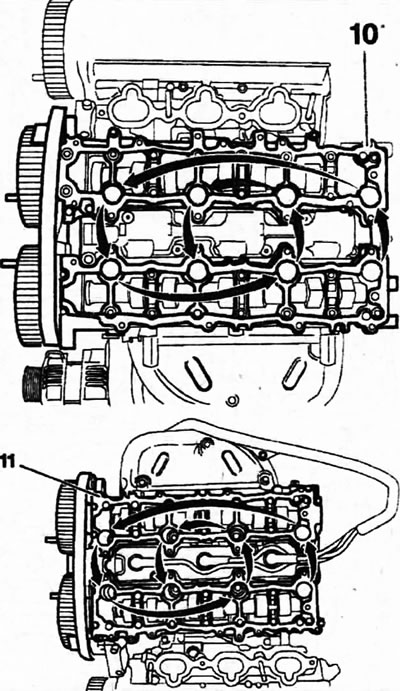
4.52. Unscrew the cylinder head mounting bolts, acting in a spiral, and remove, depending on necessity, the cylinder head 10 or 11
53. Remove the 12 head sealing gaskets from the cylinder block (see illustration).
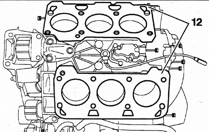
4.53. Remove the 12 head sealing gaskets from the cylinder block
Installation
54. Clean the mating surfaces of the cylinder head and block using a suitable scraper to remove any remaining gasket material and carbon deposits without damaging the surfaces.
Prevent dirt from entering the lubrication channels. Contamination can block the oil supply to the camshafts and crankshaft bearings. Cover the coolant and engine oil circulation holes, as well as the cylinder head mounting bolt holes in the cylinder block, with tape or a clean rag.
55. Clean holes 13 for the cylinder head mounting bolts (see illustration). If necessary, renew the thread with an M10x150 tap.
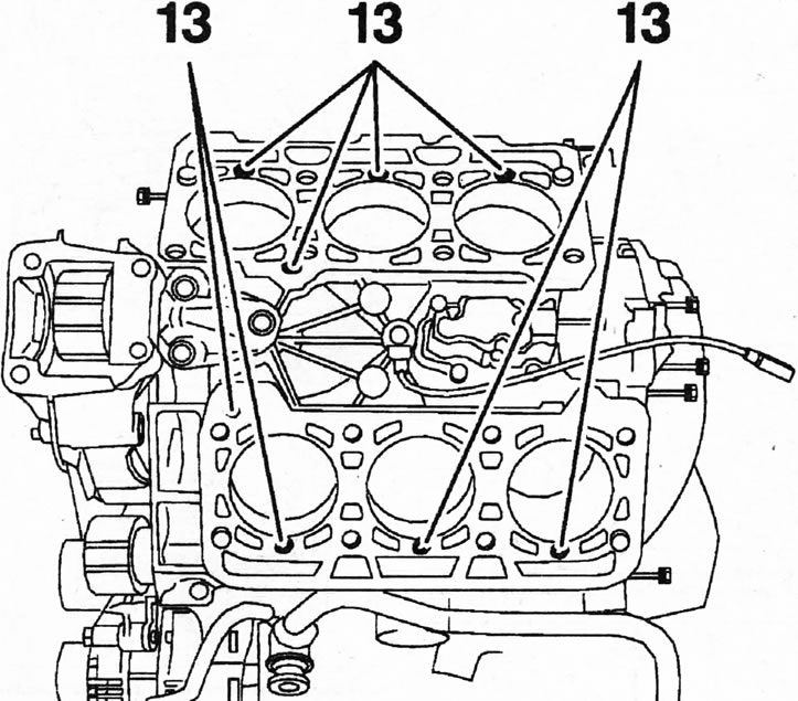
4.55. Clean holes 13 for the cylinder head mounting bolts
Caution! There must be no oil or coolant in the cylinder head bolt holes. If necessary, remove oil or liquid from the holes using a screwdriver wrapped in a rag. If oil remains in the holes, damage to the cylinder block may occur when tightening the bolts.
56. Check the cylinder head for deformation and warpage using a standard steel ruler. Place the ruler along the measurement lines (see illustration). Curvatures within 0.05 mm are allowed.
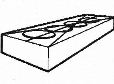
4.56. Check the cylinder head for warpage using a standard steel ruler
57. Measure the length of the cylinder head bolts and clean their threads. The length X of the bolt from the bottom surface of its head must not exceed 149.5 mm (see illustration). The length of the new bolt is 147.5±0.5 mm.
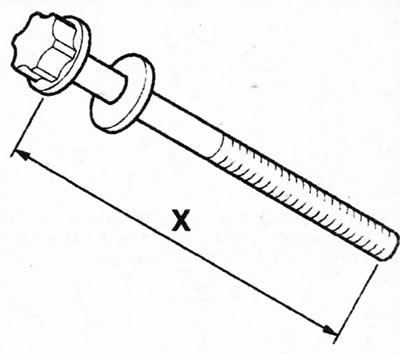
4.57. Measure the length X of the cylinder head bolts
58. Make sure that the mounting pins 14 are in their mounting holes 15, which are also free of oil or coolant (see illustration).
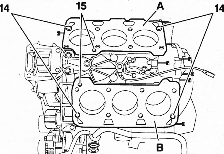
4.58. Make sure that the mounting pins 14 are in their mounting holes 15, which are also free of oil or coolant A - right cylinder head gasket; B - left cylinder head gasket
59. Place new gaskets A and B on the cylinder block (see illustrations 4.58 and 4.59). The gaskets must be positioned so that no openings are covered.
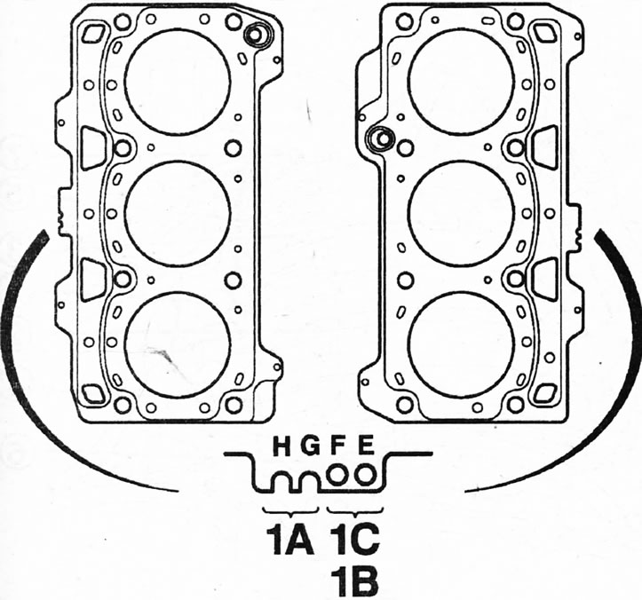
4.59. Sealing gaskets of the right and left cylinder heads. Cars with the ES9J4S engine 1A - engine designation; 1B - nominal thickness (0.75 mm); 1A - engine designation; 1B - nominal thickness (0.75 mm)
60. Install the head on the cylinder block, or both if both heads were removed.
61. Apply a thin coat of MOLYKOTE G RAPID PLUS grease to the threads and the underside of the cylinder head bolt head (see arrows in the illustration).
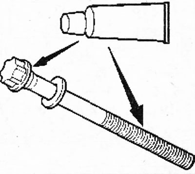
4.61. Apply a thin layer of MOLYKOTE G RAPID PLUS grease to the threads and the underside of the cylinder head bolt head (see arrows)
62. Tighten the cylinder head bolts in several passes in the sequence shown in the illustration:
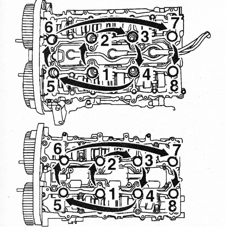
4.62 Cylinder head bolt tightening sequence
- 1st pass - tighten the bolts to 20±1 Nm,
- 2nd pass - completely loosen the bolts;
- 3rd pass - tighten the bolts to 15±1 Nm;
- 4th pass - tighten the bolts an additional 225°.
Attention! Cylinder head cover gaskets are composite; minor damage to gaskets can be repaired by applying SILICONE CATEGORIE 2 sealant
63. Install the cylinder head covers, tighten the bolts in several passes in ascending order of their numbering (see illustrations 6.32 and 6.32a):
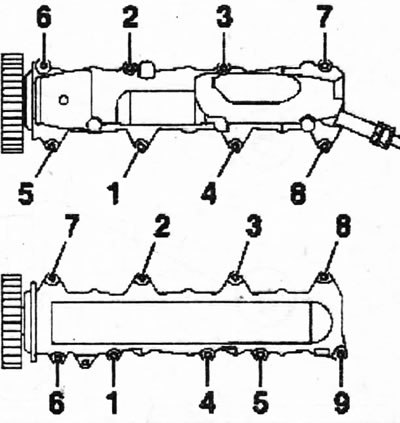
4.63. Bolt tightening sequence
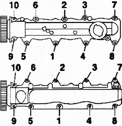
4.63a Sequence of tightening the bolts securing the left cylinder head cover
- 1st pass - screw in and tighten the bolts by hand;
- 2nd pass - tighten the bolts to 5±0.3 Nm;
- 3rd pass - tighten the bolts to 10±1 Nm.
64. Install all removed components in the reverse order of removal.
65. Connect the upper part of the intake manifold, installing a new sealing gasket, and tighten the mounting bolts in ascending sequence of their numbers (see illustration).
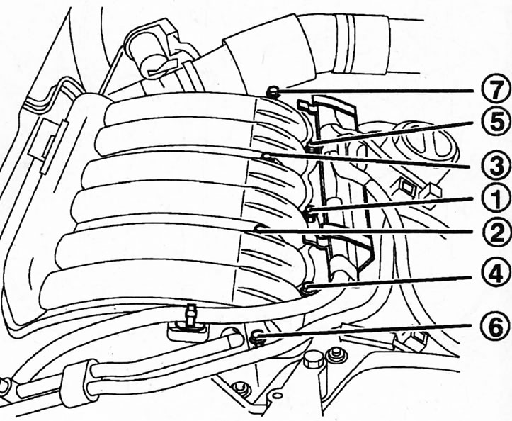
4.65. Connect the upper part of the intake manifold and tighten the mounting bolts in ascending order of their numbers
66. Connect the lower part of the intake manifold with a new gasket and also tighten the mounting bolts in the sequence of their numbers (see illustration).
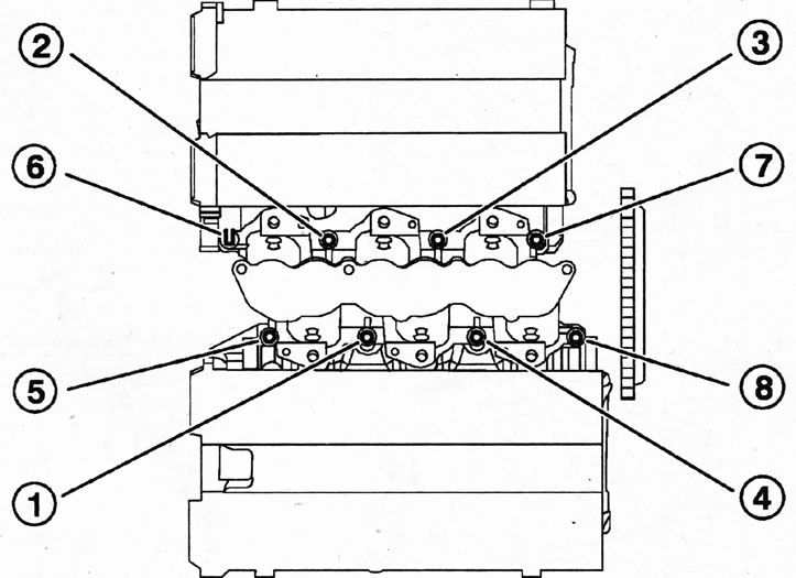
4.66 Connect the lower part of the intake manifold with a new gasket and also tighten the mounting bolts in the sequence of their numbers
67. Install the exhaust manifolds onto the cylinder heads, replacing the old sealing gaskets with new ones and tightening the bolts in the indicated numbering (see illustration). (see illustration).
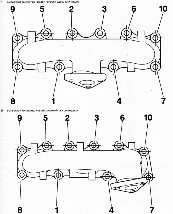
4.67. Install the exhaust manifolds onto the cylinder heads, tightening the bolts in the indicated order