



Table of contents: Disassembly 🠇 Assembly 🠇
Attention! Disassembly and assembly are shown using the EW12J4 engine as an example
Disassembly
1. Remove the oil filler neck chamber 3 (see illustration).
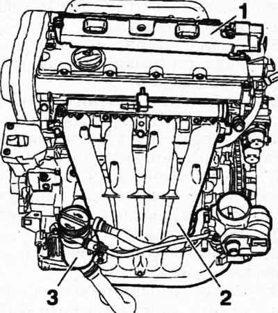
7.1. Remove the oil filler neck chamber 3
2. Unscrew the eight bolts securing the intake manifold 2 and remove it together with the throttle valve mounting bracket and injector rail.
3. Disconnect the plug, unscrew the mounting bolts and remove block 1 of the ignition coils (see illustration 7.1).
4. Disconnect the oil filter 6 and the oil filter bracket 7 together with the engine oil cooling radiator (see illustration).
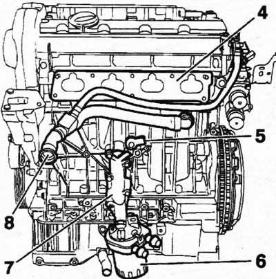
7.4. Disconnect the oil filter 6 and the oil filter bracket 7 together with the engine oil cooling radiator
5. Unscrew the 5 fuel knock sensor (see illustration 7.4).
Information copied from the resource: www.PeugeotBook.ru
6. Remove the sealing gasket 4 of the manifold and disconnect the crankcase ventilation pipe 8 (see illustration 7.4)
7. Unscrew bolts 9 securing the pressure plate 10 of the clutch to the flywheel and remove the clutch (see illustration).
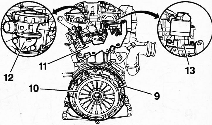
7.7. Unscrew bolts 9 securing the pressure plate 10 of the clutch to the flywheel and remove the clutch
8. Remove bracket 11 (see illustration 7.7).
9. Unscrew the mounting bolts and remove the electromagnetic 13 and mechanical 12 valves of the exhaust gas recirculation system (see illustration 7.7).
10. Unscrew the nuts and remove the thermostat housing 14 and its sealing gasket 15 from the cylinder head, disconnecting the outlet hose 16 (see illustration).
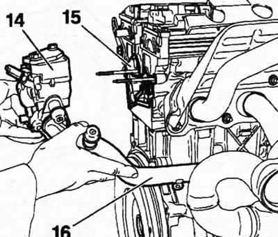
7.10. Unscrew the nuts and remove the thermostat housing 14 and its sealing gasket 15 from the cylinder head, disconnecting the outlet hose 16
11. Unscrew the ten nuts 18 securing the exhaust manifold 17, remove the heat shield 19 and the exhaust manifold together with the sealing gasket (see illustration).
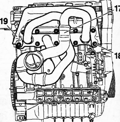
7.11. Unscrew the ten nuts 18 securing the exhaust manifold 17, remove the heat shield 19 and the exhaust manifold
Tightening torque 35±3 Nm.
12. Disconnect the camshaft position sensor 23 (see illustration).
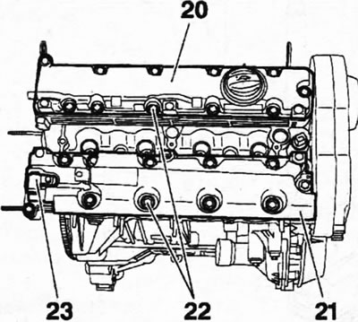
7.12. Disconnect the camshaft position sensor 23
13. Unscrew bolts 22 securing both parts 20 and 21 of the cylinder head cover and remove the cover (see illustration 7.12).
14. Unscrew bolts 27, which secure pulley 28 of the auxiliary drive V-belt to the timing gear drive gear, and remove the pulley from the crankshaft (see illustration).
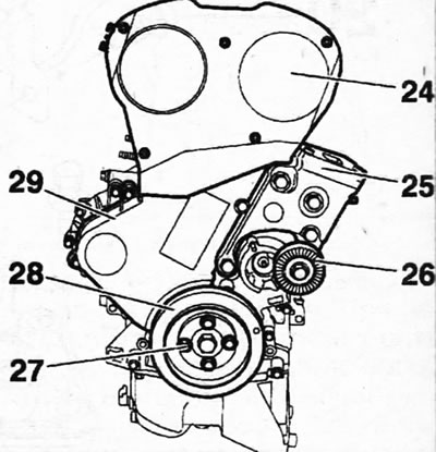
7.14. Unscrew bolts 27 and remove pulley 28 of the accessory drive V-belt from the crankshaft
15. Unscrew the mounting bolt and remove the V-belt tension roller 26 (see illustration 7.14).
16. Disconnect the left suspension support bracket 25 from the cylinder block (see illustration 7.14).
17. Unscrew the mounting bolts and remove both parts 24 and 29 of the timing gear protective cover (see illustration 7.14).
18. Fix the crankshaft with thrust roller 2, inserting it into the hole on the cylinder block and into the hole aligned with it on the crankshaft cheek (see illustration). If necessary, the engine can be turned by the central bolt securing the drive gear until these holes are aligned.
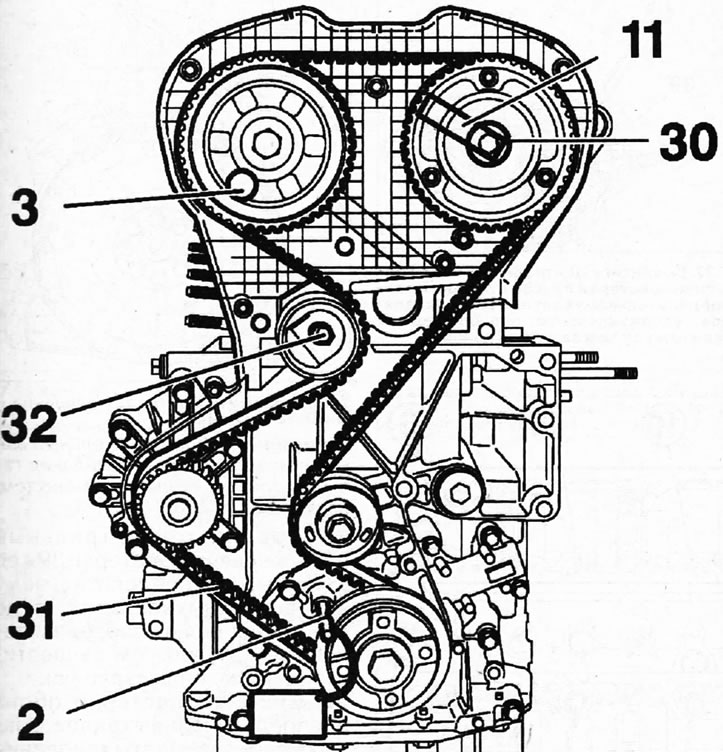
7.18. Fix the crankshaft with thrust roller 2, inserting it into the hole on the cylinder block and into the hole aligned with it on the crankshaft cheek
19. Fix the intake and exhaust camshafts by inserting appropriate stop pins 3 or pins of suitable diameter into the aligned holes on the gears and cylinder head (see). illustration 7.18).
Attention! In workshops, the intake camshaft is locked with a special roller 11 in the shape of the letter "G" (see illustration 7.18), since the shaft position regulator is attached to the gear hub of this shaft.
20. Loosen the tightening of the bolt 32 securing the timing belt tension roller, turn the roller eccentric clockwise to loosen the tension of the timing belt, and remove the timing belt 31 (see illustration 7.18).
21. Lock the flywheel with a special roller 1 by inserting it into the hole on the flywheel (see illustration).
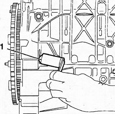
7.21. Lock the flywheel with a special roller 1, inserting it into the hole on the flywheel
22. Unscrew bolt 34 and remove guide roller 35, as well as tension roller 37 (see illustration).
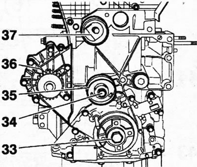
7.22. Unscrew bolt 34 and remove guide roller 35, as well as tension roller 37
23. Unscrew the mounting bolts and remove the water pump 36 (see illustration 7.22).
24. Loosen the tightening of the central bolt 33 securing the timing gear drive gear to the crankshaft (see illustration 7.22).
Caution! Thrust roller 2, which was used to lock the crankshaft when removing the timing belt, must be removed before unscrewing the central bolt. Its use as a device to prevent crankshaft rotation is not permitted. For this purpose, the flywheel was locked with a corresponding roller.
25. Remove the rollers that were used to secure the camshafts before removing the timing belt, and also remove the plug 30 from the end of the intake camshaft position adjuster (see illustration 7.18).
26. Unscrew the central bolt securing the camshaft of the intake valves of the regulator 38 and its gear (see illustration).
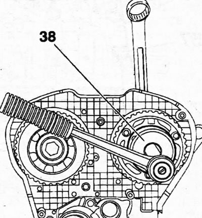
7.26. Unscrew the central bolt securing the camshaft of the intake valves of the regulator 38 and its gear
Caution! Hold the camshaft from turning with a hex wrench (see illustration 7.26a).
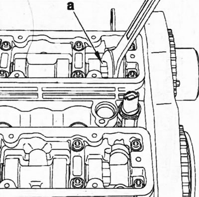
7.26a. Hold the camshaft from turning using the hex key
27. Unscrew the central bolt securing gear 39 and its hub to the exhaust camshaft, also holding the shaft from turning with a hex wrench (see illustration).
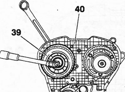
7.27. Unscrew the central bolt securing gear 39 and its hub to the exhaust camshaft, holding the shaft from turning with a hex wrench
28. Remove the gears of both camshafts, then unscrew the mounting bolts and remove the rear cover 40 of the timing drive (see illustration 7.27).
29. Unscrew the mounting bolts 42 and remove the flywheel 41, pulling out the stop with which the flywheel was locked (see illustration).
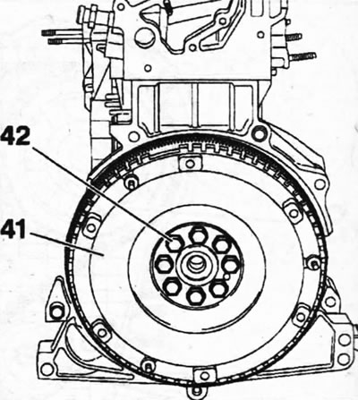
7.29 Unscrew the mounting bolts 42 and remove the flywheel 41
30. Unscrew the bolts 43 securing the cylinder head 44, acting in ascending order of their numbering, and remove the head and its sealing gasket from the cylinder block (see illustration).
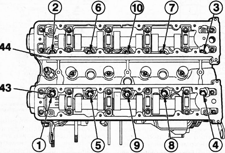
7.30. Unscrew the bolts 43 securing the cylinder head 44, acting in the order of increasing numbering, and remove the head from the cylinder block
Caution! To remove the cylinder head from the block, workshops use special lifting levers.
31. Remove the oil pan if it has not been removed previously.
32. Unscrew the sixteen bolts 56 (M6) securing the main bearing housing, ten bolts 57 (M11) of the main bearing caps, acting in ascending order of numbering, and remove the main bearing housing 58 (see illustration).
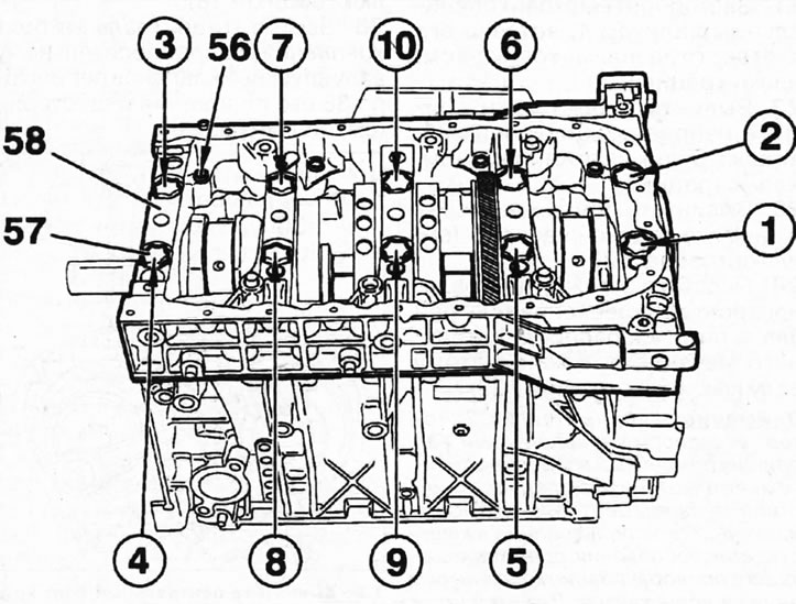
7.32. Remove the main bearing housing 58 by unscrewing bolts 56 and 57
33. Remove the connecting rod bearing caps, take out the crankshaft 61, thrust half rings 60 and main bearing shells 59 (see illustration).
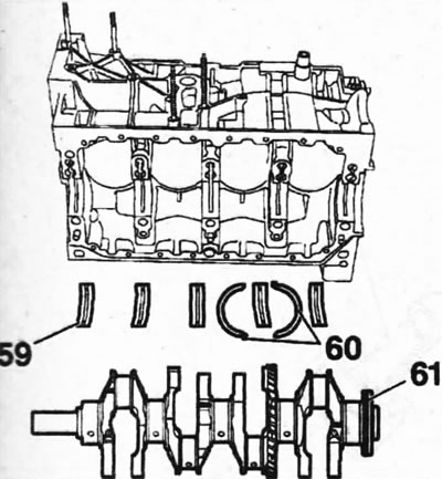
7.33. Remove crankshaft 61, thrust half rings 60 and main bearing shells 59
Attention! The crankshaft is sealed with oil seals at both ends. Before removing the crankshaft, it is recommended to measure the value of its axial runout in order to prepare thrust half rings of the appropriate repair size in advance, if necessary.
34. Remove the pistons and connecting rods from the cylinder block and remove the oil scraper and compression rings from the pistons using the appropriate tool (see illustration). If these same rings are to be installed again, they should be marked so that they can be returned to their original locations.
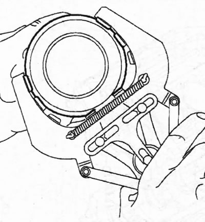
7.34. Remove the oil scraper and compression rings from the pistons using an appropriate tool
Caution! Mark pistons and connecting rods and their mounting locations before removal.
35. Separate the pistons and connecting rods by pressing out the piston pins. The piston pin can be pressed out with a striker by installing the piston in a special press (see illustration).
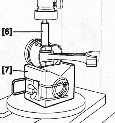
7.35. Separate the pistons and connecting rods by pressing out the piston pins
Assembly
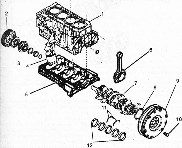
7.0. Cylinder block and its components. Engine EW10J4/EW12J4 1 - cylinder block; 2- pulley of the V-belt for auxiliary drive; 3-drive gear of the timing mechanism; 4 - oil filter; 5 - main bearing housing; 6 - connecting rod assembly with bearing cap; 7 - crankshaft; 8 - oil seal; 9 - flywheel; 10 - flywheel mounting bolt; 11 - thrust half rings; 12 - main bearing shells
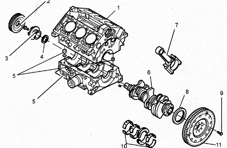
7.0a Cylinder block and its components. Engine ES9J4S 1 - cylinder block; 2 - pulley of the V-belt for auxiliary drive; 3 - leading gear of the gas distribution mechanism; 4 - oil seal; 5 - main bearing housing; 6 - crankshaft; 7 - connecting rod assembly with bearing cap; 8 - oil seal; 9 - flywheel mounting bolt; 10 - main bearing shells; 11 - flywheel
Inspect all parts carefully. If their surfaces show signs of corrosion, scratches, or their wear has reached acceptable limits, then such parts must be replaced.
The cylinder block consists of a crankcase and a crank mechanism (main bearing housings) and the cylinder block itself.
When completely disassembling, thoroughly clean the cylinder block and remove all foreign particles from the cavities and lubrication channels. The liquid used to flush and clean the unit must be completely removed. If possible, dry the unit with compressed air after cleaning. Make sure that no oil gets into the cylinder head bolt holes. If oil is found in the holes, be sure to remove it.
The warpage of the cylinder block surface is checked in the same way as on the cylinder head. Measure the cylinder block surface in the longitudinal, transverse and diagonal directions using a steel ruler. The thickness of the measuring template (gauge), which can freely fit under the installed ruler, should not exceed 0.05 mm.
Measure the piston ring clearances in the grooves by sequentially inserting the rings into the corresponding groove on the piston. The gap size is determined using a template inserted into the gap between the working edge of the ring and the surface of the groove on the piston. If the gap size is not within specification, either the rings or the pistons are worn.
After checking and making any necessary replacements of the connecting rod and piston group parts, the pistons and connecting rods are assembled.
36. Make sure the crank arms are not twisted or bent. To do this, check the connecting rod in the appropriate installation. Twisted or bent connecting rods will adversely affect engine performance. We recommend that this check be performed in a workshop. The connecting rod caps must be tightened with bolts so that the gap A between their halves is at least 1 mm (see illustration).
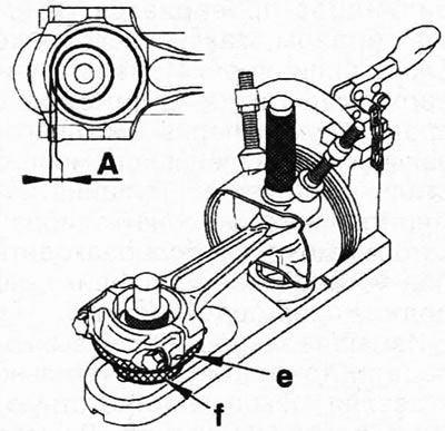
7.36. Adjust the position of the piston and connecting rod on a special device before installing the piston pin to maintain their alignment, securing the piston so that the holes for the piston pin coincide with the hole on the device
37. Make sure that when connecting the piston and connecting rod, the oil hole "h" on the connecting rod will be positioned as shown in the illustration.
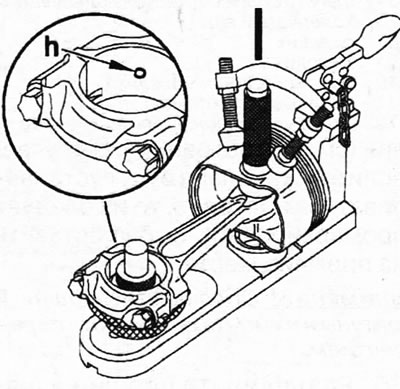
7.37. Make sure that when connecting the piston and connecting rod, the oil hole "h" on the connecting rod will be positioned as shown in the illustration
38. Remove the connecting rod from the fixture and place the connecting rods on an electric hotplate to warm them up. It is recommended to lay the connecting rods on the tile in a star shape so that only the connecting rod heads are heated. Place a piece of solder "g" on the connecting rods near their heads, this will allow you to control the heating temperature of the heads, which should not exceed 250°C (see illustration).
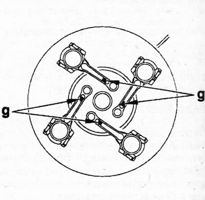
7.38. Place the connecting rods on a hotplate to heat their heads g - solder
39. Prepare the piston pin for assembly by placing it on the piston pin installation shaft. Do not tighten the shaft too tightly to avoid jamming when the pin expands from contact with the heated connecting rod. Lubricate the piston pin thoroughly with engine oil.
40. Grasp the heated connecting rod with pliers and insert it into the piston secured in a special device.
41. Push the piston pin, previously secured to the roller, into the piston hole up to the shoulder on the roller and hold it in this position until the connecting rod cools down (see illustration). When pushing the pin into the hole, make sure that the holes in the connecting rod head and in the piston are aligned so that the pin fits correctly. If necessary, move the connecting rod to maintain alignment.
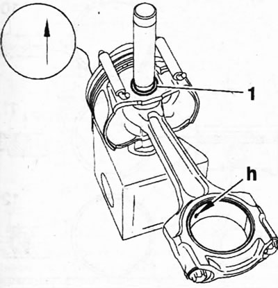
7.41. Push the piston pin, previously secured to the shaft, into the piston hole up to the shoulder on the shaft and hold it in this position until the connecting rod cools down h - lubrication hole
Caution! To ensure proper connection of the pin to the connecting rod, press the pin in place. As soon as possible, since the connecting rod cools quickly and after cooling it will not be possible to change the position of the pin.
42. Remove the piston with the connecting rod from the fixture a few seconds after pressing in the piston pin, and make sure that the piston moves freely on the connecting rod after the connecting rod has cooled.
43. Unscrew the piston pin installation shaft, screw the next piston pin onto it and connect the next piston and connecting rod in the same way.
Caution! Remove any melted solder from the connecting rod.
44. Secure the 3-cylinder block to a workbench or assembly stand so that the upper 6 main bearing shells can be installed, using the marks made during engine disassembly. The upper bearing shells have grooves for lubricating the bearings with engine oil (see illustration).
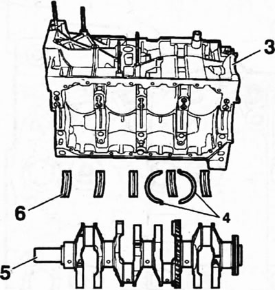
7.44. Secure the 3 cylinder block to a workbench or mounting stand so that the upper 6 main bearing shells can be installed
45. Place crankshaft 5 into the cylinder block after installing the upper liners, lubricating the shaft journals with engine oil (see illustration 7.44). Turn the shaft several times to ensure the bearings are seated.
46. Install both thrust half rings 4 on the second bearing, counting from the rear side of the engine (see illustration 7.44).
The oil grooves must face the crank arm.
47. Install the 8 main bearing housing onto the cylinder block and tighten the ten bolts 7 with a force of 10 Nm (see illustration).
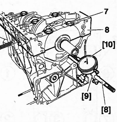
7.47. Install the 8 main bearing housing onto the cylinder block and tighten the ten bolts 7
48. Attach a support with a dial indicator to the cylinder block and check the axial runout of the crankshaft by pushing the shaft from the opposite side (see illustration 7.47). The axial runout of the crankshaft should be within 0.06 - 0.15 mm.
49. Unscrew bolts 7, remove main bearing housing 8 and replace thrust half rings of the appropriate thickness.
Caution: Before installing the main bearing housing, ensure that the "j" centering pins are in their mounting locations and protrude approximately halfway. If necessary, replace the pins with new ones (see illustration 7.49).
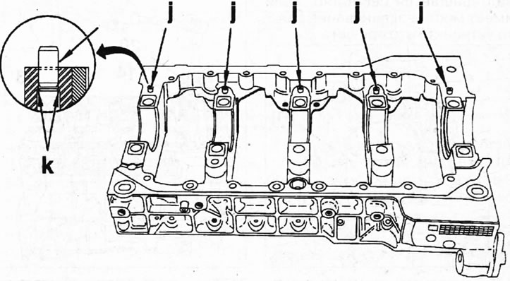
7.49. Make sure the "j" dowel pins are in their mounting locations on the main bearing housing and protrude approximately halfway
50. Apply AUTOJOINT NOIR sealant to the edges of the main bearing housing 8, install the housing on the cylinder block and screw in bolts 7 and 9, then tighten them in several passes. Bolts 7 are tightened in ascending order of their numbering (see illustration).
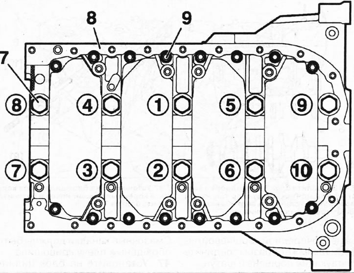
7.50. Install the main bearing housing onto the cylinder block and secure it with bolts, tightening them in several passes
- 1st pass. Tighten bolts 7 to a torque of 10±1 Nm.
- 2nd pass. Tighten bolts 9 to a torque of 2±1 Nm.
- 3rd pass. Completely loosen bolts 7.
- Pass 4. Tighten bolts 7 to a torque of 20±1 Nm.
- Pass 5. Tighten bolts 7 by 70°
- Pass 6. Tighten bolts 9 to 10±1 Nm.
51. Make sure the crankshaft rotates freely. If the shaft is jammed, eliminate the cause.
52. Install the oil scraper and compression rings onto the pistons using a suitable tool. The lower compression ring 11 must be positioned so that the inscription "TOP" on it faces upwards, towards the bottom of the piston. The locks of the upper compression ring 10 and the lower 11 must be turned 180° relative to each other. Oil scraper ring 12 does not have a lock (see illustration).
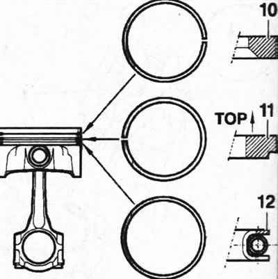
7.52. Install the oil scraper 12 and compression rings 10 and 12 on the pistons using the appropriate tool
53. Install the mounting sleeve 11 onto the piston, which is needed to compress the piston rings when installing the pistons into the cylinders. The bushing should be positioned on the piston so that the lower part of the piston skirt protrudes (see illustration).
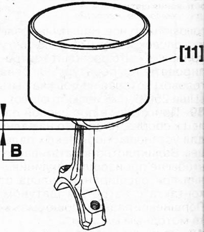
7.53. Fastening the mounting sleeve 11 to the piston before installing it in the cylinder
54. Install the upper connecting rod bearing shells.
55. Lubricate the cylinder surfaces with engine oil and install the pistons into the cylinders. The arrow on the bottom of the pistons must point towards the timing drive (see arrow in illustration).
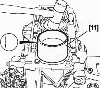
7.55. Lubricate the cylinder surfaces with engine oil and install the pistons into the cylinders
56. Place the cylinder block on the workbench with the crankcase facing up and install the connecting rod bearing caps, placing the lower bearing shells lubricated with engine oil.
57. Lubricate the threads of bolts 13 securing the connecting rod bearing caps with engine oil, screw them in and tighten them in several passes with a torque wrench 14. Since the bolts will need to be turned to a certain angle, it is recommended to use template 20 (see illustration).
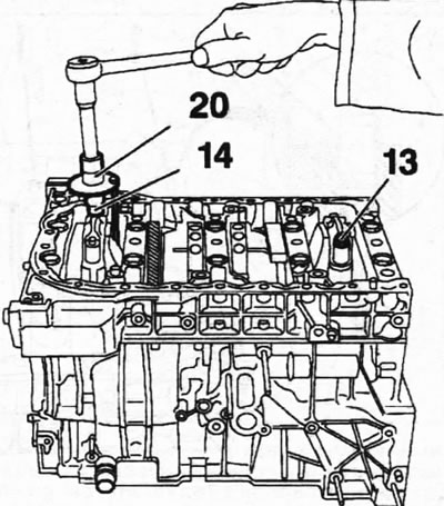
7.57. Lubricate the threads of bolts 13 fastening the connecting rod bearing caps with engine oil
- 1st pass. Tighten bolts 13 with a torque of 23±1 Nm.
- 2nd pass. Tighten bolts 13 by 45°±5°.
58. Install oil pump 14, applying AUTOJOINT NOIR sealant to the sealing surfaces of its cover (see illustration).
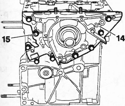
7.58. Install oil pump 14, applying AUTOJOINT NOIR sealant to the sealing surfaces of its cover
59. Screw in nine new oil pump mounting bolts 15, lubricating their threads with LOCTITE FRENETANCH paste, and tighten them with a force of 8±1 Nm (see illustration 7.58).
60. Fit the front 16 and rear 17 crankshaft oil seals using a suitable mandrel 1 (see illustration).
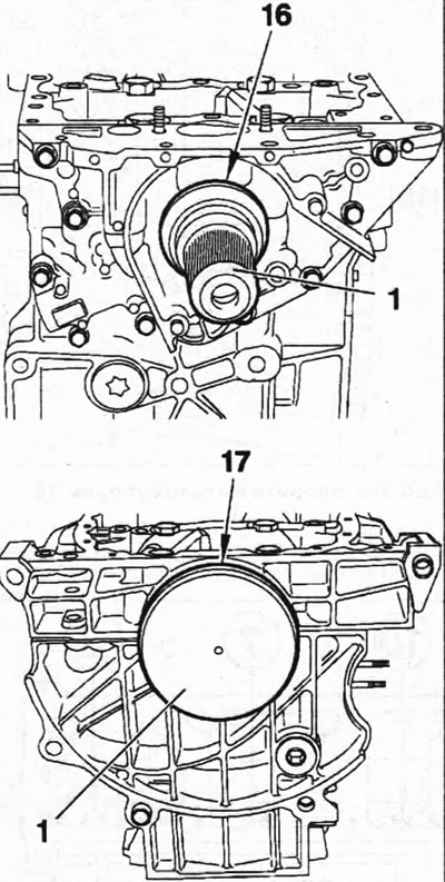
7.60. Fit the front 16 and rear 17 crankshaft oil seals using a suitable mandrel 1
61. Install the oil intake tube 23 with a mesh filter, replacing the old oil intake sealing gasket with a new one (see illustration).
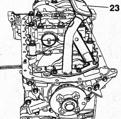
7.61. Install oil intake tube 23 with a mesh filter, replacing the old oil intake sealing gasket with a new one
62. Make sure that the "m" pin, which centers the oil pan on the cylinder block, is in its hole on the block (see illustration).
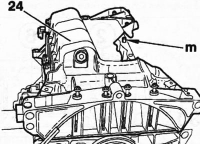
7.62. Make sure that the "m" pin, which centers the oil pan on the cylinder block, is in its hole on the block
63. Apply AUTOJOINT NOIR sealant to the surface of the cylinder block where the oil pan is mated, install the oil pan 24 and center it so that its edges are flush with the surface of the cylinder block (see illustration 7.62).
64. Screw in nineteen bolts 26 and seven bolts 25 for fastening the oil pan 24 and tighten them with a force of 8±2 Nm (see illustration).
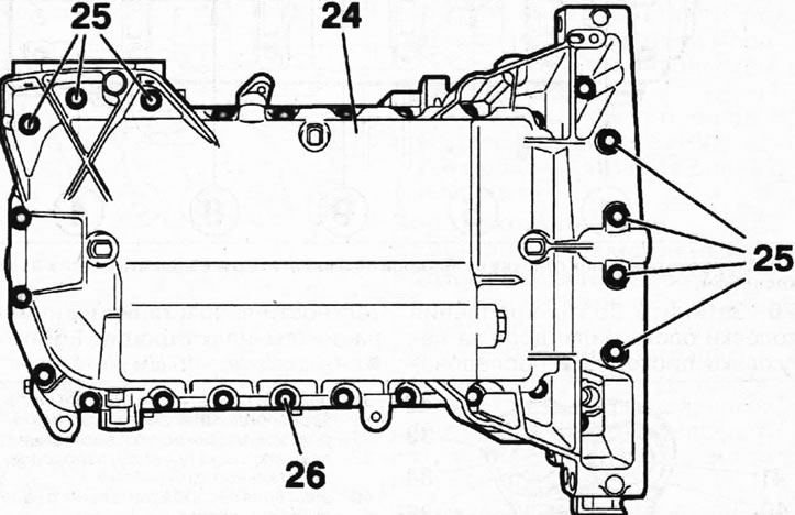
7.64. Screw in nineteen bolts 26 and seven bolts 25 for fastening the oil pan 24 and tighten them with a force of 8±2 Nm
65. Install flywheel 27 on the crankshaft and secure it with new bolts 28, screwing them in by hand until the heads touch(see illustration).
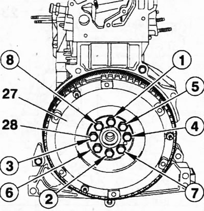
7.65. Install flywheel 27 on the crankshaft and secure it with new bolts 28
66. Lock.the flywheel.with stop 16 (see illustration).
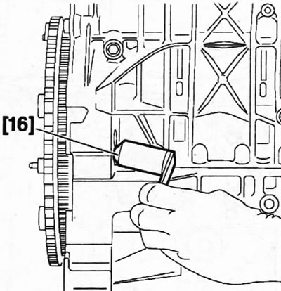
7.66. Stop the flywheel with stop 16
67. Tighten the flywheel mounting bolts to 2072 Nm, then turn them further by 26°±3°, acting in the sequence of increasing their numbering (see illustration 7.65).
68. Make sure that the "p" pins that center the head on the cylinder block are in their seats on the block, and place the new head sealing gasket 29 on the block with the TOP marking facing up (see illustration).
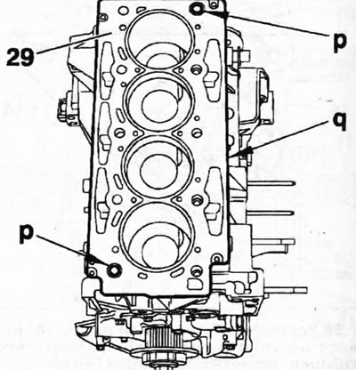
7.68. Make sure that the "p" pins, which center the head on the cylinder block, are in their seats on the block, and place a new head sealing gasket 29 on the block
69. Install the assembled cylinder head 30 onto the block and screw in the ten bolts 31 of its fastening by hand (see illustration). Lubricate the bolt threads with MOLYKOTE G RAPID PLUS sealant.
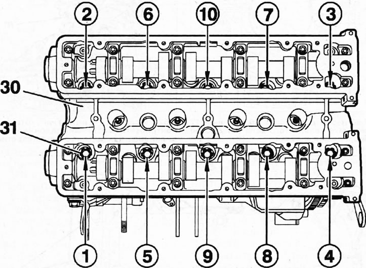
7.69. Install cylinder head 30 on the block and screw in ten bolts 31 of its fastening by hand
Caution! Before installing the cylinder head, rotate the crankshaft and position the pistons approximately in the center of the cylinders.
70. Tighten the cylinder head bolts in several passes in ascending order of their numbers (see illustration 7.69):
- 1st pass - 15 Nm;
- 2nd pass - 50 Nm;
- 3rd pass - loosen the bolts one full turn;
- 4th pass - 20 Nm;
- 5th pass - tighten the bolts an additional 270°.
Attention! The turn to the specified angle can be performed in two steps.
71. Install the water pump and secure it with bolts, tightening them in ascending numbered order in several passes (see illustration):
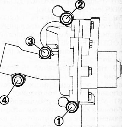
7.71 Install the water pump and secure it with bolts
- 1st pass - 3±1 Nm;
- 2nd pass - 8±1 Nm;
- 3rd pass - 14±1 Nm;
72. Install the timing drive components (see illustration).
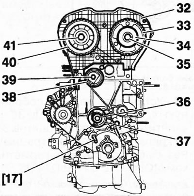
7.72. Install the timing drive components 38 - timing belt tension roller; 39 - tension roller mounting bolt; 32 - rear cover of the timing drive; 40 - exhaust camshaft gear; 41 - central bolt for fastening the gear to the shaft; 34 - intake camshaft position adjuster; 33 - intake camshaft gear; 35 - central bolt for fastening the regulator and gear to the camshaft. The bolt must be replaced with a new one; 37 - guide roller; 36 - guide roller mounting bolt
Attention! For the order of installing gears on camshafts, see. in the relevant chapter.
73. Lock the crankshaft with stop 17 (see illustration 7.72).
74. Make sure that the central bolt 20 securing the drive gear 18 to the crankshaft is not tightened to the final torque and the gear can be turned on the shaft if necessary (see illustration).
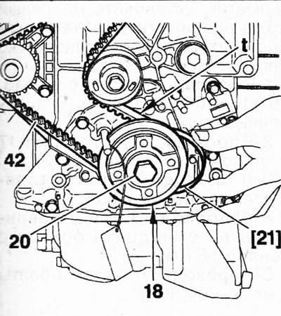
7.74 Make sure that the central bolt 20 securing the drive gear 18 to the crankshaft is not tightened to the final torque and the gear can be turned on the shaft if necessary
75. Place the toothed belt 42 on the drive gear 18 and secure it with the clamp 21, then place it on the guide roller, on the intake camshaft gear, the exhaust camshaft gear, the water pump gear and the tension roller (see illustration 7.74).
76. Adjust the timing belt tension, see the relevant chapter.
77. Install both parts 44 and 49 of the timing gear protective cover, bracket 45, tension roller 46 of the auxiliary V-ribbed belt, pulley 48 of the V-ribbed belt, which secure with four bolts with a tightening torque of 21±2 Nm (see illustration).
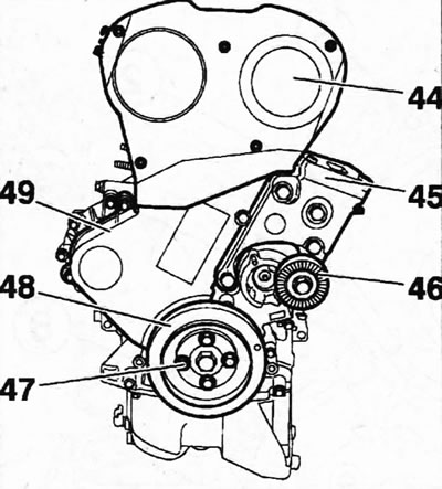
7.77. Install the timing gear cover and accessory drive components
78. Install both parts 51 and 53 of the cylinder head cover, as well as the camshaft position sensor 52, the ignition coil block 55, which is secured with three bolts 54, and screw in twenty-two bolts 50 securing the cylinder head cover (see illustration).
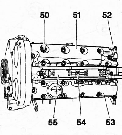
7.78. Place both parts of the cylinder head cover, install the camshaft position sensor and the ignition coil block
79. Tighten the cylinder head cover bolts 50 in ascending order of their numbering by applying a force of 11±1 Nm (see illustration).
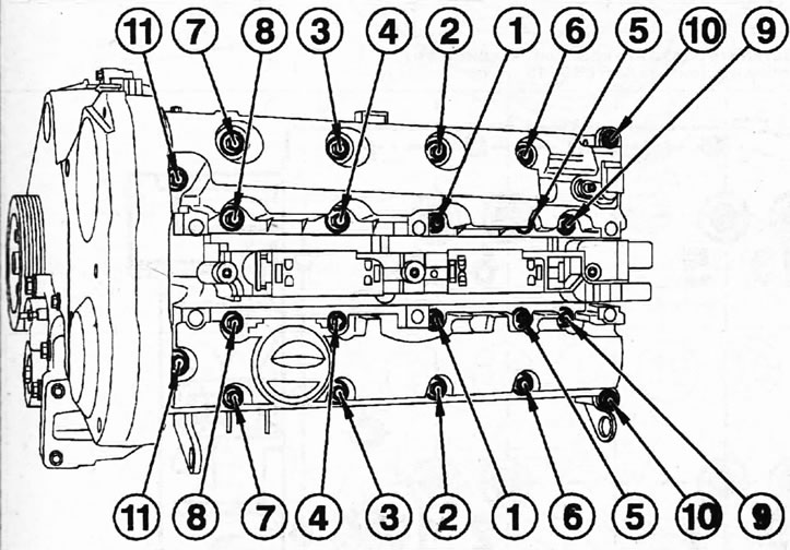
7.79. Tighten the cylinder head cover bolts 50 in ascending order of their numbering by applying a force of 11±1 Nm
80. Install the exhaust manifold, thermostat housing, EGR valves, and intake manifold.
81. Install the clutch, see the relevant chapter and connect the engine and gearbox.
Oil pump. Cars with the ES9J4S engine
82. Install the oil pump, screw in and tighten the bolts of its fastening, acting in the order of increasing their numbering, in several passes (see illustration).
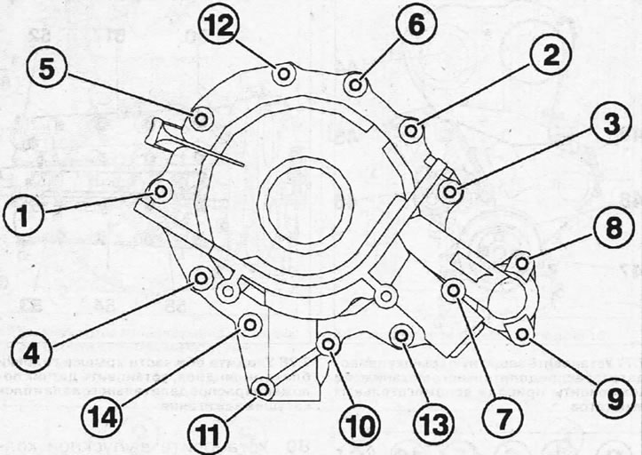
7.82. Install the oil pump, screw in and tighten the bolts of its fastening, acting in the order of increasing their numbering. Cars with the ES9J4S engine
- Pass 1: Tighten the bolts to 5 Nm.
- 2nd pass. Tighten the bolts to 8 Nm.
Main bearing housing and oil pan for the ES9J4S engine
83. Install the main bearing housing and secure it with bolts 21 (see illustration).
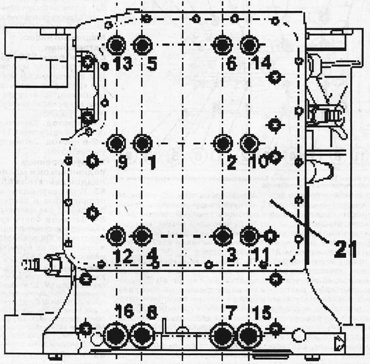
7.83. Install the main bearing housing and secure it with bolts 21. Cars with engine ES9J4S
84. Tighten the main bearing housing bolts in ascending order of their numbering (see illustration 7.82).
Please note: Bolts 21 vary in length and have different tightening levels. M11 bolts are tightened in two passes. During the first pass, the bolts are tightened to 30 Nm. During the second pass, the bolts are turned an additional 180°. M8 bolts are also tightened in two passes, but the tightening torque is 10 Nm, followed by an additional 180°.
85. Install the lubrication system components (see illustration).
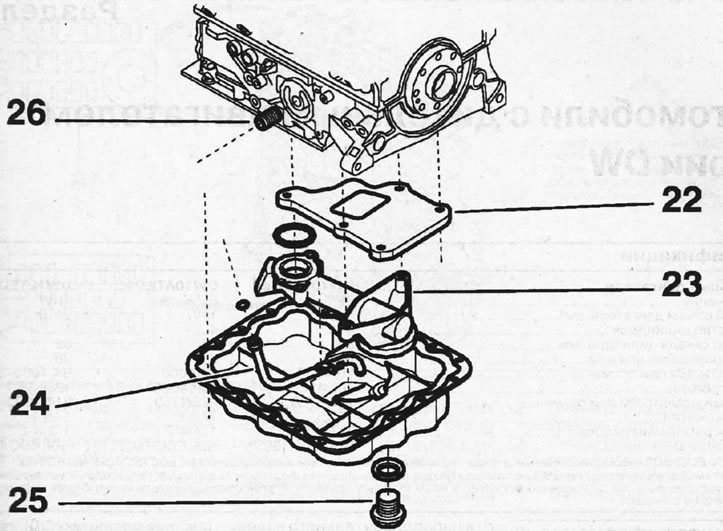
7.85. Install the lubrication system components. Cars with the ES9J4S engine 22 - oil separator; 23 - oil intake mesh filter; 24 - crankcase ventilation tube; 25 - drain plug; 26 - oil filter mounting pipe
86. Apply sealant to the sealing surface of the oil pan, install the oil pan, screw in and tighten the bolts of its fastening in several passes (see illustration).
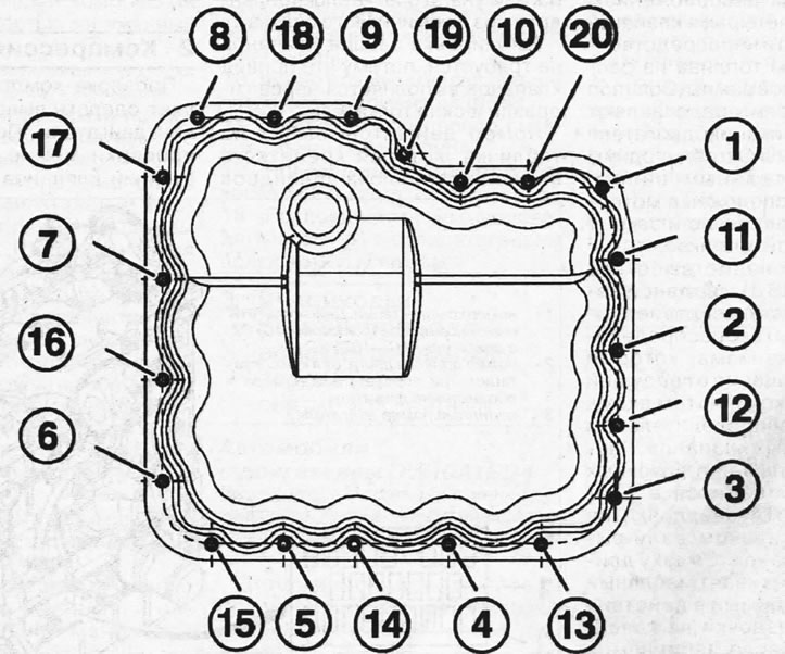
7.86. Apply sealant to the sealing surface of the oil pan, install the oil pan, screw in and tighten the bolts that secure it. Cars with ES9J4S engine.
- 1st pass. Screw in bolts 13, 15 and 17 to secure the installed tray.
- 2nd pass. Tighten 13, 15 and 17 to 2 Nm.
- Pass 3: Screw in the remaining seventeen bolts.
- Pass 4: Tighten the seventeen bolts to 5 Nm.
- Pass 5. Tighten all bolts to 8 Nm.