



Table of contents: Cars with EW10J4/EW12J4 engines 🠇 Cars with the ES9J4S engine 🠇
Important! The car owner can remove and install the engine independently, provided he has the appropriate equipment and tools. Some dismantling and installation work requires an assistant. It is recommended to entrust repairs of a removed engine or gearbox to a workshop. In specialized workshops, when removing the engine, they use a special trolley 1 with corresponding supports 2 that hold the power unit (see illustration 6.0).
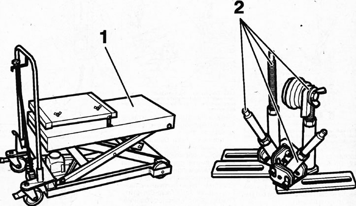
6.0. Lifting trolley and supports for fastening the removable power unit
Any clamps that are damaged or cut during engine removal must be replaced with new ones when installing the engine.
Depending on the year of manufacture and vehicle configuration, electrical wires, lines, and hoses may be located in different locations in the engine compartment. Therefore, before disconnecting plugs, lines, or hoses, it is recommended to mark them with tape or a marker so that they can be reinstalled in their original locations later.
Cars with EW10J4/EW12J4 engines
Removal
1. Disconnect the battery and place the car on jack stands.
2. Remove the front wheels, engine compartment protection, front bumper, headlights and windshield wiper.
3. Drain the coolant and oil from the gearbox, see the relevant chapter.
4. Disconnect both drive shafts from the gearbox and secure them with wire to the body so that they do not sag, see the relevant chapter.
5. Unscrew the mounting bolts and disconnect the intake pipe from the exhaust manifold, see the corresponding pipe.
6. Remove the engine protective cover, air filter, radiator hose and thermostat housing, and move the coolant expansion tank and power steering reservoir to the side.
7. Relieve pressure in the fuel system.
8. Remove the accessory drive belt, see the relevant chapter.
9. Unscrew the bolts 1 of the power steering line holder and move the power steering pump to the side without disconnecting the lines from it (see illustration).
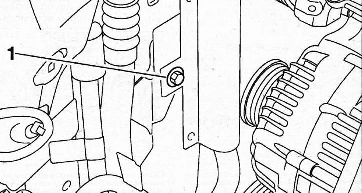
6.9. Unscrew the bolts 1 of the power steering pipe holder
10. Move aside the chamber 2 of the oil filler neck, as well as the pipes 3 of the power steering fluid cooling radiator (see illustration).
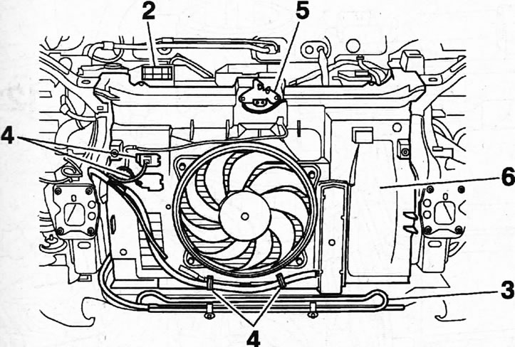
6.10. Move aside the chamber 2 of the oil filler neck, as well as the pipes 3 of the power steering fluid cooling radiator
11. Disconnect the radiator fan plug 4, release the fan wiring harness from the holders and move the wires to the side (see illustration 6.10).
12. Disconnect the drive cable from the hood latch 5 and also move it to the side (see illustration 6.10).
13. Disconnect the hoses from the radiator, unscrew the mounting bolts and remove the radiator and its tank 6 (see illustration 6.10).
14. Unscrew the air conditioning compressor mounting bolts and move the compressor to the side without disconnecting the refrigerant circulation lines from it.
Caution! Do not open the refrigerant circuit. All work related to opening the air conditioning system should be entrusted to a specialized workshop.
15. Vehicles with EW12J4 engine. Disconnect fuel supply line 7 and line 8 of the purge solenoid valve of the adsorber (see illustration).
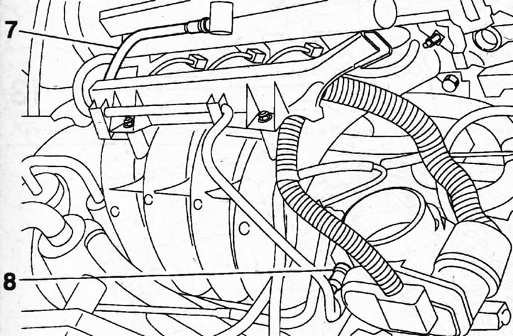
6.15 Disconnect the fuel supply line 7 and the line 8 of the purge solenoid valve of the adsorber. Cars with EW12J4 engine
16. Cars with EW10J4 engine. Disconnect fuel supply line 9, line 10 of the purge solenoid valve of the adsorber and accelerator cable 11 (see illustration).
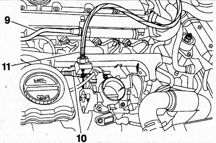
6.16. Disconnect the fuel supply line 9, the line 10 of the electromagnetic valve for purging the adsorber and the accelerator cable 11. Cars with EW10J4 engine
17. Disconnect the low pressure hose 13 from the EGR valve and the EGR pipe into the intake manifold (see illustration).
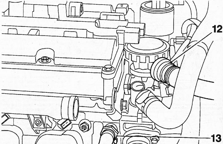
6.17. Disconnect the low pressure hose 13 from the EGR valve and the EGR pipe into the intake manifold
18. Disconnect the low pressure hose from the brake booster.
19. Disconnect the supply and return hoses from the heater radiator.
20. Disconnect plugs 14 from the fuse and relay box, which is located near the right headlight, as well as wire 15 "ground" (-) and move the engine wiring harness away from the work area (see illustration).
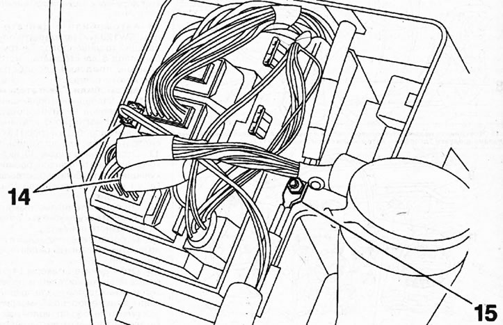
6.20. Disconnect plugs 14 from the fuse and relay box, as well as wire 15 "ground" (-) and move the engine wiring harness away from the work area
21. Release the clutch slave cylinder pressure line from the holder, and then disconnect the slave cylinder.
22. Disconnect plugs 16 and wires 17 "ground" (-) (see illustration).
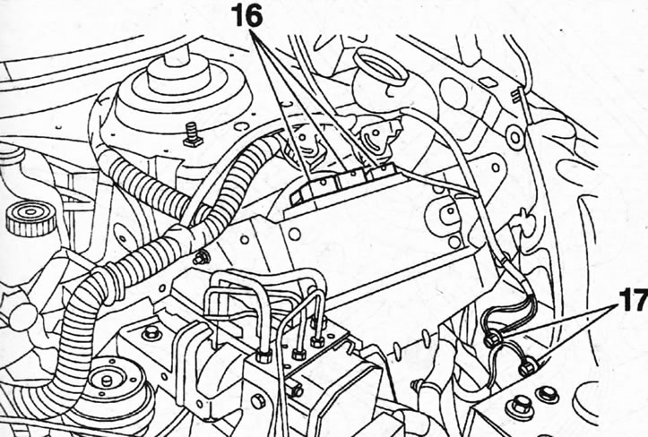
6.22. Disconnect plugs 16 and wires 17 "ground" (-)
23. Disconnect the gear selection and shift cables, the reversing light switch plug and the ground (-) wire from the gearbox.
24. Remove the subframe.
25. Disconnect the lambda probe connectors and disconnect the lower cooling line located near the oil pan.
26. Place a lifting trolley 1 or garage jack under the power unit and slightly lift the power unit to relieve the load on the suspension supports (see illustration).
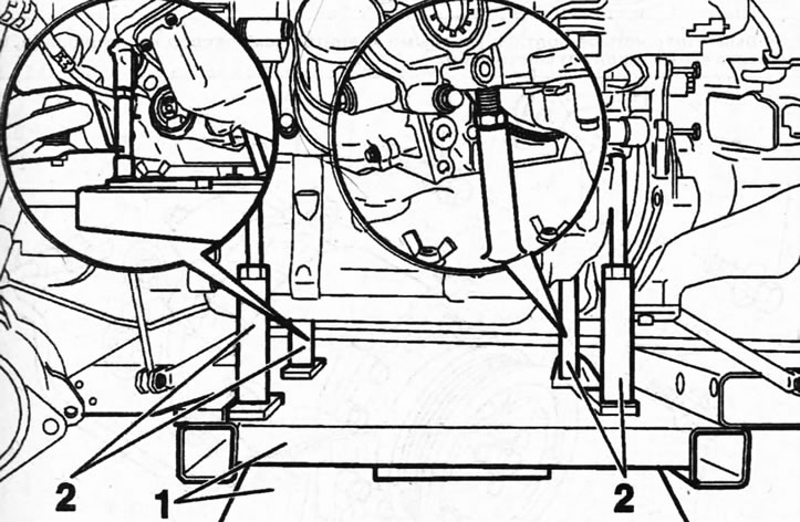
6.26. Fastening the power unit to the lifting trolley 2 - racks on a trolley
27. Disconnect the lower engine mount support (see illustration).
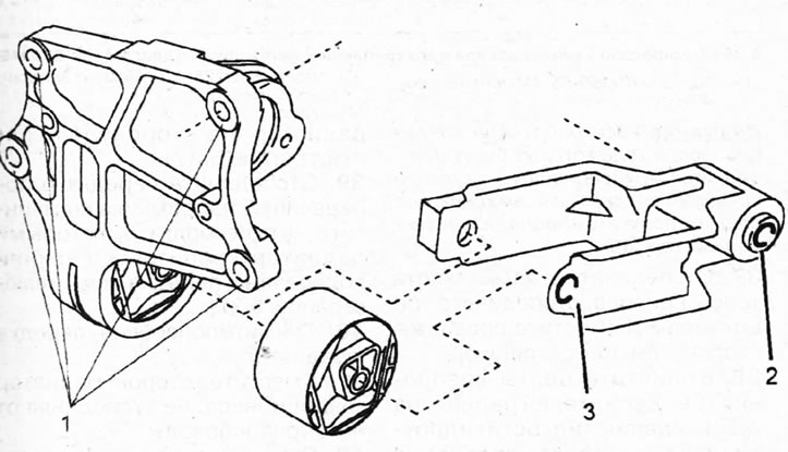
6.27. Disconnect the lower engine mount support 1 - bolts for fastening the lower support bracket to the cylinder block. Tightening torque 45 Nm; 2 - bolt for fastening the support bracket to the subframe. Tightening torque 90 Nm; 3 - central support mounting bolt. Tightening torque 65 Nm
28. Disconnect the engine mount torque rod (see illustration 2.4a).
29. Disconnect the left support of the power unit suspension (see illustration).
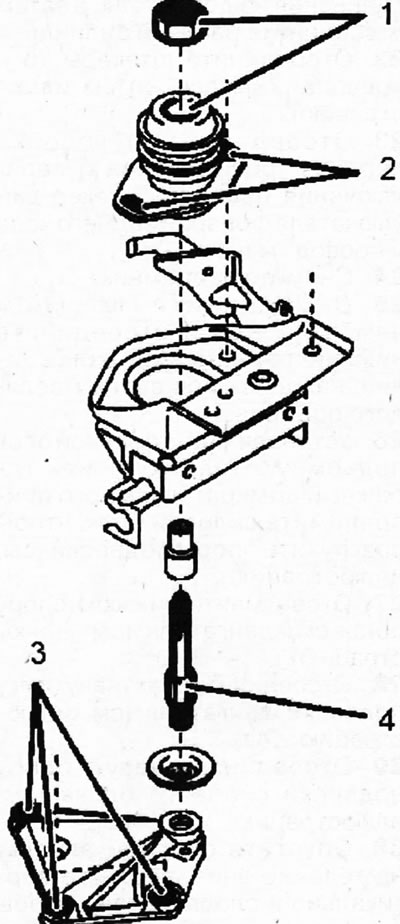
6.29. Left support of the power unit suspension 1 - nut for fastening the support pin to the body. Tightening torque 30 Nm; 2 - support; 3 - bolts for fastening the support bracket to the gearbox. Tightening torque 45 Nm; 4 - central support bolt. Tightening torque 50 Nm
30. Lower the power unit on the trolley downwards, moving it vertically and making sure not to catch any nearby parts and assemblies.
31. Place the removed power unit on appropriate supports and, if necessary, disconnect the gearbox from the engine by unscrewing the connecting bolts.
The installation of the power unit is carried out in the reverse order of removal.
Cars with the ES9J4S engine
Removal
32. Disconnect the battery and relieve pressure in the fuel system.
33. Drain the coolant, see the relevant chapter.
34. Place the car on jack stands and remove the front wheels, fender liners, front bumper and its cross member.
35. Remove the auxiliary drive V-belt, see the relevant chapter.
36. Unscrew the four bolts 1 that secure the air conditioning compressor and move it away from the work area without disconnecting the refrigerant circulation lines from it (see illustrations 6.36 and 6.36a).
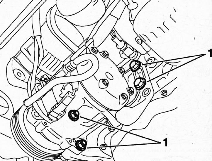
6.36. Unscrew the four bolts 1 that secure the air conditioning compressor and move it away from the work area
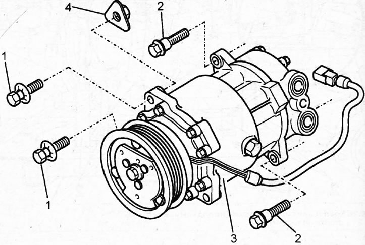
6.36a. Air conditioning compressor 3 and its fastening. Cars with the ES9J4S engine 1 - bolts M10x150-55. Tightening torque 40 Nm; 2 - bolts M8x125-110. Tightening torque 2575 Nm; 4 - nut
Caution! All work on the air conditioner that involves disconnecting the refrigerant lines and draining the refrigerant itself should be left to a specialized workshop.
37. Disconnect the hood lock cable 2, disconnect the three plugs 3 and move the wires to the side (see illustration).
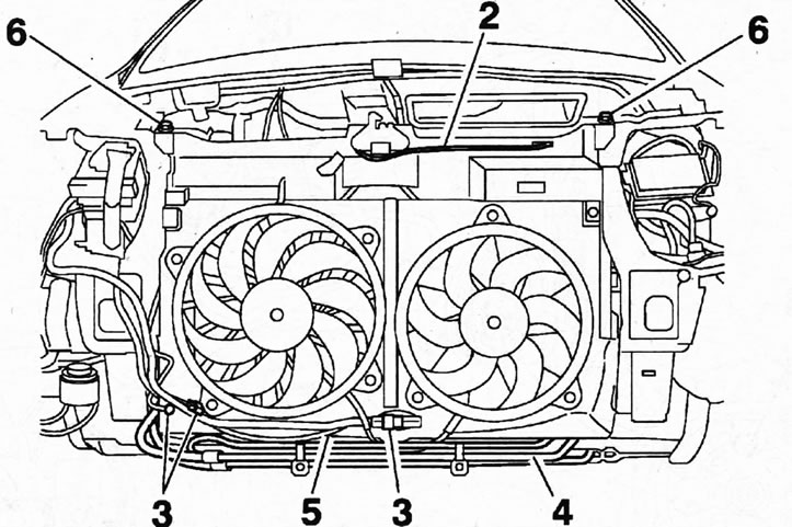
6.37. Disconnect the drive cable 2 from the hood lock, disconnect the three plugs 3 and move the wires to the side
38. Unscrew the bolts securing the three holders of the power steering fluid cooling radiator 4 to the subframe 5 and move the radiator 4 to the side (see illustration 6.37).
39. Disconnect the front cross member 5 of the subframe and unscrew the four bolts 6 that secure the radiator to the upper cross member of the front (see illustration 6.37).
40. Remove the front cross member and radiator.
41. Move the air conditioner radiator to the side without disconnecting the pipes from it.
42. Remove the windshield wiper and intake manifold by releasing the hoses from the holders on the intake and exhaust manifolds.
43. Disconnect the selector plug and the end of the cable 7 for selecting and shifting gears, and then release the cable 7 from the holder 8 (see illustration).
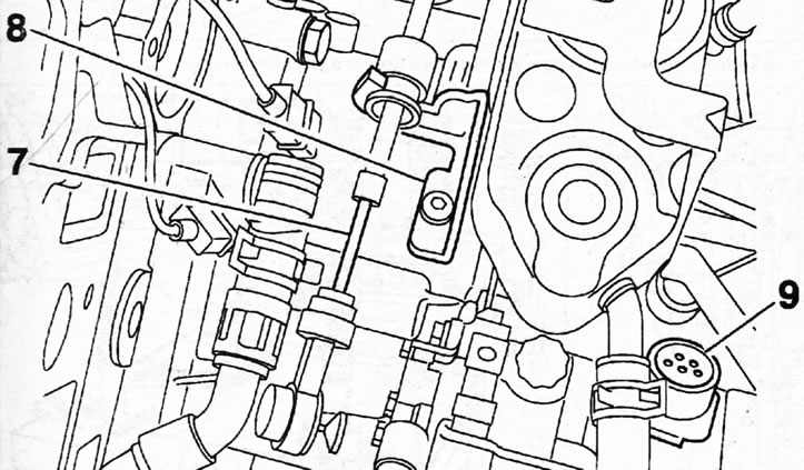
6.43. Disconnect the end of the gear selection and shift cable 7 from the selector, and then release the cable 7 from the holder 8
44. Disconnect plug 9 and the ground (-) wire from the gearbox housing (see illustration 6.43).
45. Disconnect and move aside the fuel lines.
46. Disconnect the two connectors 10 and 11 and remove the power steering reservoir (see illustration).
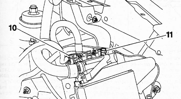
6.46. Disconnect the two plugs 10 and 11
47. Disconnect the intake pipes with pre-catalysts from the exhaust manifolds, see the relevant chapter.
48. Disconnect the right and left drive shafts from the gearbox and secure them with wire to the body so that they do not sag, see the relevant chapter.
49. Unscrew two bolts 12, and then 3 bolts 13 securing the power steering pump (see illustration).
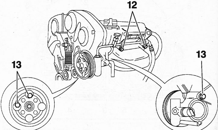
6.49. Unscrew two bolts 12, and then 3 bolts 13 securing the power steering pump
50. Move the power steering pump to the side and, without disconnecting the pipes from it, secure it to the body or place it on an appropriate support.
Caution! Release the power steering line from the holder on the rear cylinder head by unscrewing the two holder bolts.
51. Place a lifting trolley 1 or garage jack under the power unit and secure the unit to the trolley supports 2 (see illustration).
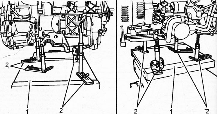
6.51. Place a lifting trolley 1 or garage jack under the power unit and secure the unit to the trolley supports 2
52. Raise the power unit on the trolley to relieve the load on the suspension supports.
53. Unscrew three bolts 15, bolts 18 and 19, unscrew nut 14 and disconnect the reaction rod 17 and its bracket 16 (see illustration).
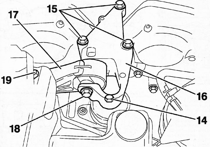
6.53. Unscrew three bolts 15, bolts 18 and 19, unscrew nut 14 and disconnect the reaction rod 17 and its bracket 16
54. Disconnect the power unit suspension support by unscrewing six bolts 20 and unscrewing nut 21 (see illustration).
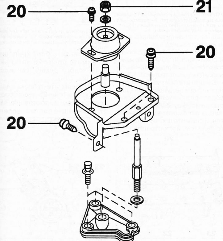
6.54. Disconnect the power unit suspension support by unscrewing six bolts 20 and unscrewing nut 21
55. Lower the power unit onto the lifting dolly and remove it from under the vehicle. If necessary, unscrew the bolts securing the gearbox to the engine and disconnect the gearbox.
Installation of the power unit is carried out in the reverse order of removal.
Caution! When installing, replace the exhaust pipe connecting clamps, metal gaskets of the pre-catalysts, self-locking nuts, and nuts securing the downpipes/pre-catalysts with new ones.