



Table of contents: Removal 🠇 Outer CV joint - replacement 🠇
Torque from the gearbox to the drive wheels is transmitted via drive shafts, which, due to the gearbox being shifted to the left, have different lengths. Each drive shaft consists of inner and outer constant velocity joints (CV joints) and the shaft itself. The splined part of the outer joint (shank) is inserted into the wheel hub and secured with a hub nut, and the inner joint is attached to the gearbox. CV joints are lubricated with consistent grease, which is added only when the joint is disassembled.
The condition of the CV joint boots should be checked periodically, because if they are damaged, the lubricant will leak out and dirt will get into the CV joint itself, causing it to be damaged.
Important! Since the oil seals that seal the holes into which the drive shaft ends are inserted will need to be replaced with new ones before installing the shafts, a suitable mandrel will be required to press the oil seals in. When installing the shaft end into the seal, use the protective guides that are sometimes included with the seals.
When removing the drive shaft, other parts will also become disconnected. Therefore, you should prepare a new hub nut, a tie rod end ball joint nut, and new nuts for the shock absorber strut mounting bolts to the steering knuckle in advance.
Removal
1. Jack up the front of the vehicle, remove the corresponding front wheel and unscrew the hub nut 3, removing the cotter pin 1, removing the slotted lock washer 2 and holding the hub from turning with a suitable device 4 (see illustration).
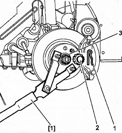
10.1. Unscrew the nut 3 of the front wheel hub by pulling out the cotter pin 1, removing the crown seal 2 and holding the hub from turning with a suitable tool 4
Caution! Do not hold the front wheel hub while loosening the hub nut with the foot brake, as this may damage the brake disc mounting bolt.
2. Disconnect the ABS sensor to avoid damaging it during the process of removing the shafts.
3. Cars with manual transmission. Drain the transmission oil from the box.
The automatic transmission is sealed, so there is no need to drain the oil when disconnecting the drive shaft.
4. Unscrew the nuts of the bolts 1 with which the shock absorber strut 2 is secured to the steering knuckle and remove the bolts (see illustration). Before removing the bolts, mark which side the bolts are inserted from. Before unscrewing the nuts and bolts and disconnecting the strut, make sure that the car stands firmly on jack stands.
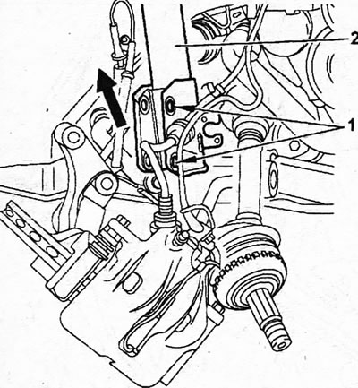
10.4. Unscrew the nuts of the bolts 1 with which the shock absorber strut 2 is secured to the steering knuckle and remove the bolts
5. Press the steering knuckle down to release the strut.
Caution! When disconnecting the shock absorber strut from the steering knuckle, be careful not to damage the protective corrugated CV joint boot. It is recommended to wrap the CV joint boot with a thick cloth.
Right drive shaft
6. Unscrew as much as possible, but do not remove nuts 1 from the bolts securing the intermediate support of the right drive shaft (see illustration). Tightening torque of nuts 100 Nm.
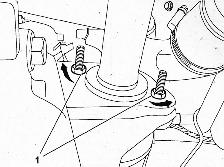
10.6. Unscrew, but do not remove, nuts 1 from the bolts securing the intermediate support of the right drive shaft
7. Turn the intermediate support mounting bolts 1/4 turn to move their eccentrically located heads away from the outer edge of the bearing (see illustration 10.6).
8. Push the steering knuckle outward and the drive shaft inward, thus removing the drive shaft end from the hub (see illustration). When the left axle shaft is disconnected, the steering knuckle rotates to the left, and the right axle shaft rotates to the right. It's possible that the shaft end fits tightly in the hub, requiring a hammer (plastic or rubber), and also a punch or a soft metal roller to knock the hub off the shank.
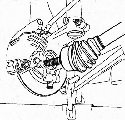
10.8. Push the steering knuckle outward and the drive shaft inward, thus removing the drive shaft end from the hub
Caution! After removing the drive shaft from the hub, secure it to the body with wire to prevent it from sagging and damaging the gearbox hole under its own weight. Alternatively, attach the shock absorber strut to the steering knuckle using a single 5-gauge bolt if the drive shaft will not be installed for a long time (see illustration 10.8a).
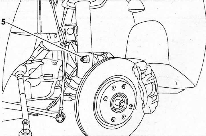
10.8a. Secure the shock absorber strut to the steering knuckle with one bolt if the drive shaft will not be installed for a long time
Installation of the axle shafts is carried out in the reverse order of removal.
9. Inspect the drive shafts and their CV joint boots. On the right axle shaft, check the condition of the support bearing. Also, ensure that the rubber on the CV joint boots is not pulled inward and that the boots themselves are securely fastened with clamps to the small and large diameter mounting belts (see illustration). If necessary, overhaul the CV joints.

10.9. Inspect the drive shafts and boots of the 2 CV joints
10. Remove the drive shaft/differential seals. The drive shaft seal can be removed from a manual gearbox by screwing two self-tapping screws into it 1 (see illustration 10.10), and on an automatic one - with the help of a mandrel (see illustration 10.10a) or knock it out with a punch (see illustration. 10.10b).
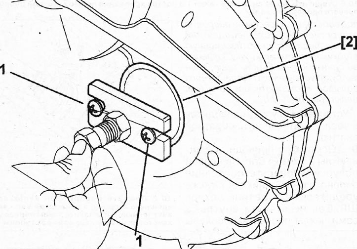
10.10. Remove the drive shaft seal from the manual gearbox using self-tapping screws 1
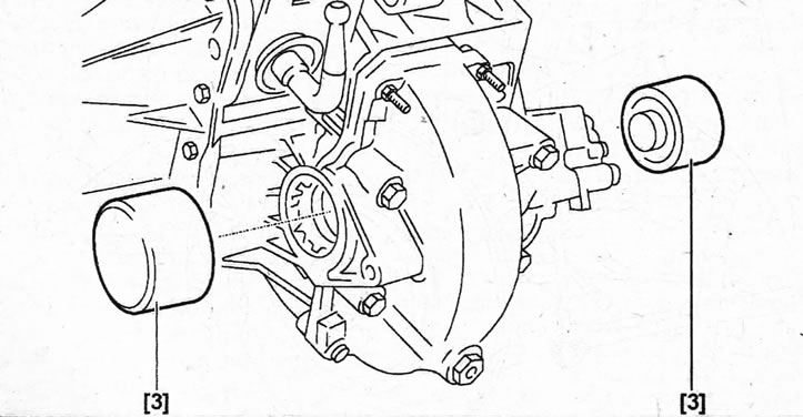
10.10a. Remove the drive shaft seal from the automatic transmission using a drift
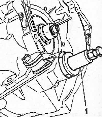
10.10b. Remove the drive shaft seal from the automatic transmission using a punch
11. Clean and lubricate the splines of the hub and drive shaft shank, as well as the intermediate support bearing of the right half-axle, with general-purpose grease.
12. Drive new oil seals into the drive shaft holes on the gearbox using the appropriate mandrels 3 and lubricating the working edges of the oil seals (see illustrations 10.12, 10.12a).
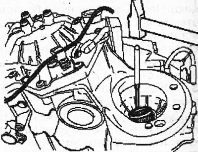
10.12. Drive new seals into the drive shaft holes on the gearbox using the appropriate mandrels 3. Cars with a manual transmission
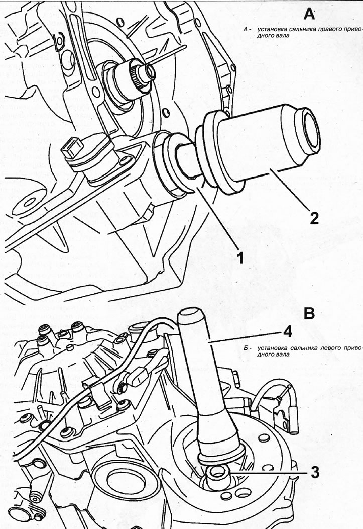
10.12a. Drive new seals 1 and 3 into the drive shaft holes on the gearbox, using the corresponding mandrels 2 and 4. Cars with automatic transmission
13. Install the drive shafts. When installing the right drive shaft, make sure that the dust cap 1 and sealing ring 2 are on the shaft (see illustration).
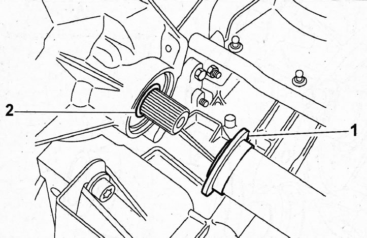
10.13. Make sure that the dust cap 1 and sealing ring 2 are present on the shaft when installing the right drive shaft
14. Cars with manual transmission. Fill the gearbox with transmission oil.
Outer CV joint - replacement
15. Remove the axle shaft and secure it in a vice, placing soft metal spacers on the jaws.
16. Remove both clamps 1 and 2 securing the cover by cutting them with side cutters, and move the cover itself onto the shaft (see illustration).
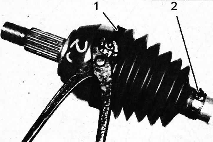
10.16. Remove both clamps 1 and 2 securing the cover by cutting them with side cutters, and move the cover itself onto the shaft
The joint is locked on the shaft with a retaining ring, so it is usually knocked off the seating place using a hammer, a soft metal drift or an impact-type puller.
17. Knock the joint off the shaft using a hammer, a soft metal drift or an impact-type puller (see illustration).
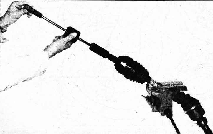
10.17. Knock the joint off the shaft using an impact-type puller
18. Remove the retaining ring 1 from the groove on the axle shaft by knocking down the joint (see illustration). When installing the CV joint, it is necessary to use a new retaining ring.
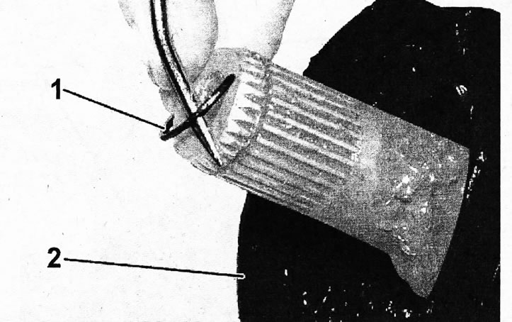
10.18. Remove the retaining ring 1 from the groove on the axle shaft
Caution! If the retaining ring is broken, the CV joint must be replaced.
19. Remove the protective rubber boot 2 from the drive shaft, clean the CV joint using an appropriate product to remove as much grease as possible (see illustration 10.18).
Caution! Do not use solvent to clean the CV joint or its boot.
20. Inspect the race, separator, and the balls themselves, making sure there is no damage to them or to the ball tracks. Make sure the balls move easily.
If any part of the hinge is worn or damaged, it should be replaced with a new one as a set.
21. Slide the new outer joint boot onto the shaft, wrapping the splines of the tailstock with tape or electrical tape to avoid damaging the small diameter belt of the boot on the edges of the splines.
22. Secure the new retaining ring into the axle shaft groove.
23. Align the splines of the joint and the axle shaft, then press the joint onto the shaft until it is secured with a retaining ring.
24. Fill the joint with grease from the repair kit, rotating the shaft around its axis so that the grease enters the bearing race. The remaining grease is stuffed into the cover.
25. Secure the cover to the hinge by inserting the edges of the cover into the grooves on the axle shaft and hinge, then install clamps 1 on the large and then small diameter belts and secure them by clamping them with special pliers 3 (see illustrations 10.25 and 10.25a).
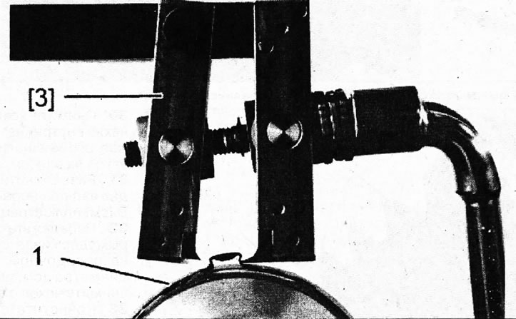
10.25. Fasten clamps 1 to the small and large diameter seating belts, clamping them with special pliers 3
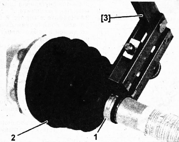
10.25a. Tighten the clamp on the small diameter CV joint boot seat
26. Before tightening the clamp, pull back the seat belt of the boot to equalize the pressure in the boot by prying it with a small screwdriver and tighten the clamp.
27. Make sure the CV joint moves smoothly and install the axle shaft.
Inner CV joint
28. Remove the drive shaft.
29. Disconnect the outer CV joint and remove its boot, wrapping the shaft splines with tape to prevent damage to the boot.
30. Remove clamp 7 securing inner CV joint boot 8 by loosening it with pliers 4 and move the boot onto the shaft (see illustration).
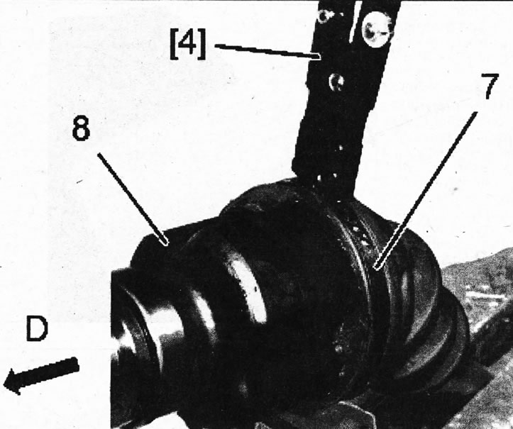
10.30. Remove clamp 7 securing inner CV joint boot 8 by loosening it with pliers 4
31. Disconnect the shaft and the CV joint by moving the shaft in the direction of arrow D (see illustration 10.30).
32. Cut the clamp 10, which holds the CV joint boot 9 on the small diameter seat belt (see illustration) and remove the cover from the shaft.
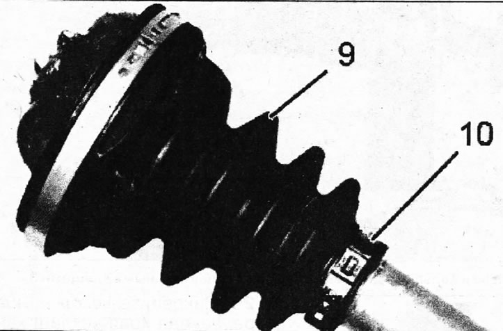
10.32. Remove clamp 10, which holds CV joint boot 9 on the small diameter seat belt
33. Clean the removed CV joint and inspect it for wear and damage. If there are any defects, the inner CV joint is replaced as a set.
34. Fill the 8 CV joint housing with the entire amount of grease included in the repair kit (see illustration).
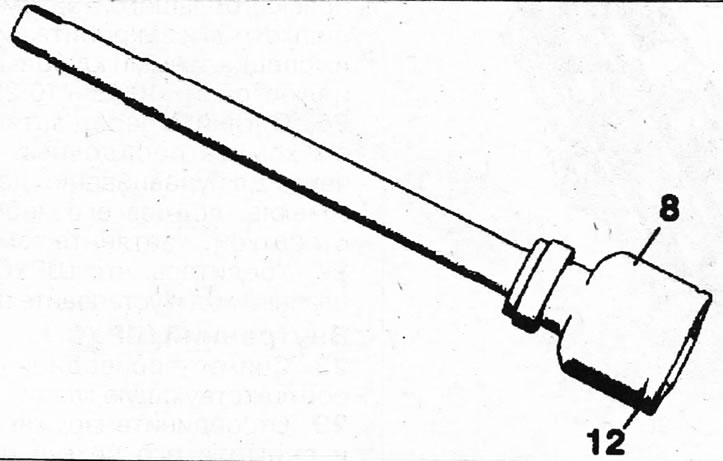
10.34. Fill the 8 CV joint housing with the entire amount of grease included in the repair kit 12 - a groove on the body into which the cover is inserted
35. Place the inner CV joint boot 9 on shaft 11, then connect it to the housing, insert the boot into the groove and tighten its clamp, equalizing the pressure inside the boot.
36. Fasten the cover 5 with a clamp 10 on the small diameter seat belt 13 using the appropriate pliers (see illustration).
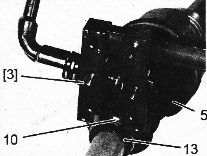
10.36. Fasten the cover 5 with a clamp 10 on the landing belt 13 of small diameter 1 using the appropriate pliers
37 Install the drive shaft.